
SLC Industrial microSD Memory Card
Engineering Specification
Document Number: L5ENG00392
Revision: C
No part of this document may be reproduced, copied, recorded, stored in a retrieval system, or transmitted in any
form without the written permission of Delkin Devices. This document is for informational use only and is subject
to change without prior notice. Delkin Devices assumes no responsibility for any errors that may appear in this
document.
© 2014 | Delkin Devices Inc.

SLC Industrial microSD Memory Card L5ENG00392 Rev. C
© 2014 | Delkin Devices Inc. 2
Table of Contents
1 Overview ........................................................................................................ 4
1.1 Product Features ....................................................................................... 4
1.2 Suggested Applications ............................................................................. 5
1.3 Specifications Summary ............................................................................ 6
1.4 Part Numbers and Availability ................................................................... 7
1.5 microSD Memory Card Read/Write Speeds .............................................. 8
2 Mechanical Specifications ............................................................................ 9
2.1 External Signal Contacts (ESC) ................................................................ 9
2.2 Design and Format .................................................................................... 9
2.3 Reliability and Durability .......................................................................... 10
2.4 Electrical Static Discharge (ESD) requirements ...................................... 10
2.4.1 Contact Pads Area ......................................................................... 10
2.4.2 Non-contact Pads Area .................................................................. 10
2.5 Mechanical Form Factor ......................................................................... 11
3 microSD Card System Concept .................................................................. 16
3.1 Rewritable or Read-only Memory Cards ................................................. 16
3.2 Card Capacity ......................................................................................... 16
3.3 Speed Class ............................................................................................ 17
3.4 Command System ................................................................................... 18
3.4.1 Send Interface Condition Command (CMD8) ................................. 18
3.4.2 Command Functional Difference in High Capacity microSDHC
Memory Card .................................................................................. 20
4 microSD Card Interface ............................................................................... 21
4.1 Pin Assignments ..................................................................................... 21
4.2 Pin Functions .......................................................................................... 21
4.3 SD Bus Topology .................................................................................... 22
4.3.1 microSD Bus Mode Protocol........................................................... 22
4.3.2 SPI Bus Mode Protocol .................................................................. 23
5 Read and Write Operations......................................................................... 25
5.1 microSD Bus Protocol ............................................................................. 25
5.1.1 Command ....................................................................................... 25
5.1.2 Response ....................................................................................... 25
5.1.3 Data ................................................................................................ 25
5.2 SPI Bus Protocol ..................................................................................... 28
5.2.1 Command ....................................................................................... 28
5.2.2 Response ....................................................................................... 28
5.2.3 Data Read ...................................................................................... 28
5.3 Card Registers ........................................................................................ 29
5.3.1 OCR Register ................................................................................. 29
5.3.2 CID Register ................................................................................... 32
5.3.3 CSD Register .................................................................................. 33
5.3.4 CSD_STRUCTURE ........................................................................ 33
5.3.5 CSD Register (CSD Version 2.0) .................................................... 33

SLC Industrial microSD Memory Card L5ENG00392 Rev. C
© 2014 | Delkin Devices Inc. 3
List of Figures
Figure 1. microSD Mechanical Description: Top and Side Views ....................... 11
Figure 2. microSD Bottom View and Keep Out Area .......................................... 12
Figure 3. microSD Adapter Top View .................................................................. 12
Figure 4. microSD Adapter Contacts .................................................................. 13
Figure 5. microSD Adapter Bottom and Side Views............................................ 13
Figure 6. Host/Card Usability .............................................................................. 17
Figure 7. microSD Contacts ................................................................................ 21
Figure 8. microSD Memory Card System Bus .................................................... 22
Figure 9. microSD Memory Card SPI System Bus.............................................. 24
Figure 10. “no response” and “no data” Operations ............................................ 25
Figure 11. Multiple Block Read Operation .......................................................... 26
Figure 12. Multiple Block Write Operation ........................................................... 26
Figure 13. Command Token Format ................................................................... 26
Figure 14. Response Token Format ................................................................... 27
Figure 15. Data Packet Format ........................................................................... 27
Figure 16. Read Operation ................................................................................. 28
Figure 17. Read Operation – Data Error ............................................................. 29
Figure 18. Write Operation .................................................................................. 29
List of Tables
Table 1. microSD Card Capacities and Part Numbers .......................................... 7
Table 2. microSD Memory Card Read/Write Speeds ............................................ 8
Table 3. microSD Memory Card Package – External Signal Contacts .................. 9
Table 4. microSD Memory Card package – Dimensions ...................................... 9
Table 5. Reliability and Durability ........................................................................ 10
Table 6. microSD Memory Card Package - Dimensions ..................................... 14
Table 7. CMD8 Format Description ..................................................................... 18
Table 8. CMD8 Card Operation .......................................................................... 19
Table 9. microSD Memory Card Pin Assignments .............................................. 21
Table 10. OCR Register Definition ...................................................................... 31
Table 11. CID Register Definition........................................................................ 32
Table 12. CSD Register Fields (Version 2.0) ...................................................... 33
Table 13. SCR Fields .......................................................................................... 37
Table 14. SCR Register Structure Versions ........................................................ 37
Table 15. Physical Layer Specification Version .................................................. 37
Table 16. SD-supported Security Algorithm ........................................................ 38
Table 17. SD Memory Card Supported Bus Widths ............................................ 38

SLC Industrial microSD Memory Card L5ENG00392 Rev. C
© 2014 | Delkin Devices Inc. 4
1 Overview
Delkin microSD cards combine a small form factor with a rugged, reliable package that’s
manufactured specifically for industrial applications. Unlike ordinary Secure Digital cards, the
Delkin microSD encapsulates all internal components to seal out dust, moisture, and electro-
static discharge and to enhance shock and vibration performance. Its industrial operating
temperature range of -40° to 85°C handles the harshest environments. Combining data-
precise Single Level Cell (SLC) components with Error Correction Code and wear leveling
algorithms gives the cards an endurance rating of 2,000,000 write/erase cycles. These RoHS-
compliant cards are also supported by Delkin’s locked-down Bill of Materials that ensures
consistent product performance and future compatibility. With outstanding read/write speeds,
these cards are ideal for automotive, security, medical, military, aviation, navigation, or any
severe-service application where dependability, durability, and data integrity are mission
critical.
1.1 Product Features
Versatility
o Targeted for portable and stationary applications
o Designed for read-only and read/write cards
o Card detection (Insertion/Removal)
o Switch function command supports High-Speed, eCommerce, and future functions
o Supports both SD and SPI modes
Capacity
o Standard Capacity microSD Memory Card: Up to and including 2GB
o High Capacity microSDHC Memory Card: 4GB, 8GB & 16GB (This version of the
specification limits capacity up to and including 32GB)
Power
o Operating voltage range: 2.7-3.6V
Current
Typical Power Required (Ta=25°@3V)
Value Notes
Stand-by 120uA Max
Read 47mA Max (varies by capacity)
Write 59mA Max (varies by capacity)
Durability
o Over 2,000,000 Write Cycles
o Global Wear Leveling
o Correction of memory field errors
o Card removal during read operation will never harm the content.

SLC Industrial microSD Memory Card L5ENG00392 Rev. C
© 2014 | Delkin Devices Inc. 5
Speed
o Default mode: Variable clock rate 0-25Mhz, up to 12.5MB/sec interface speed (using 4
parallel data lines)
o High-Speed mode: Variable clock rate 0-50 MHz, up to 25 MB/sec interface speed
(using 4 parallel data lines)
o Data transfer rate up to 25 MB/sec data transfer rate (using 4 parallel data lines).
Maximum data rate with up to 10 cards
Security
o Contact Protection Mechanism: Complies with highest security of SDMI standard
o Password Protection of cards
o Copyright protection mechanism—Complies with highest security of SDMI standard
Password Protection of cards (CMD42 –LOCK- UNLOCK)
o Write Protect feature using mechanical switch
o Built-in write protection features (permanent and temporary)
Ease of Use
o Card Detection (Insert/Remove)
o Application specific commands
o Comfortable erase mechanism
o Standard Protocol—attributes of the communication channel:
SD Memory Card Communication Channel
Six-wire communication channel (clock, command, 4 data lines)
Error-protected data transfer
Single or multiple block-oriented data transfer
o Standard Size—microSD Memory Card form factor defined in this specification
o Standard size microSD Memory Card thickness is defined as 1.0mm nominal (+/-
0.1mm).
1.2 Suggested Applications
Industrial Computers
Embedded Systems
Data Acquisition
Agriculture
Gaming
Telecommunications
Hundreds of other industries looking for a more robust and rugged digital storage option

SLC Industrial microSD Memory Card L5ENG00392 Rev. C
© 2014 | Delkin Devices Inc. 6
1.3 Specifications Summary
The following table provides a summary of the specifications critical to most engineering
solutions. For more detailed specifications, refer to the appropriate engineering specification
section.
Specification
microSD
Model number
See Table 1
Capacity
128MB – 16GB
Form factor
11mm x 15mm x 1mm
Interface
Dual protocol modes (SD and SPI)
Interface connector
8-pin @ 0-50MHz
Hot swappable
Yes
RoHS compliant
Yes
Performance
Interface burst speed
25MB/s
Sustained read transfer rate
Up to 23.0 MB/s (varies by capacity)
Sustained write transfer rate
Up to 21.4 MB/s (varies by capacity)
Reliability/Data Integrity
MTBF (power-on hours)
>2,000,000 hours
Endurance (write/erase cycles)
>2,000,000 cycles
Data Retention
>10 years
Power
Supply voltage
2.7V -3.6V
Typical power required
Ta=25°@3V
Stand-by
120uA max
Read
47mA max
Capacities ≥2GB: 120uA
Write
59mA max
Capacities ≥2GB: 120uA
Environmental
Storage temperature (°C)
-40 ~ 85°C
Operating temperature (°C)
-40 ~ 85°C
Relative humidity (non-condensing)
5 - 95%
Operating shock
40Gs at 11ms
Vibration
15Hz – 2,000Hz
Altitude
80,000 ft.

SLC Industrial microSD Memory Card L5ENG00392 Rev. C
© 2014 | Delkin Devices Inc. 7
Durability
10,000 mating cycles
Physical Dimensions
Length
15.0mm ±0.1mm
Width
11.0mm ±0.1mm
Thickness
1.0mm nominal (+/- 0.1mm See Fig. 2 C1+C3.)
Weight
0.5g typical
1.4 Part Numbers and Availability
microSD Memory Cards and adapters are available from Delkin in the capacities shown in the
table below.
Table 1. microSD Card Capacities and Part Numbers
*Note: Usable capacities are within 10% of the gross capacity figures shown above, which is typical with all NAND flash
devices, as a small portion of the total is needed for controller firmware and spare block reserves.
For capacities below 2GB, refer to document number L500487, Engineering Specification for
SLC Industrial microSD Memory Cards with SMART, available from your sales representative or at
www.delkinindustrial.com.
Capacity*
Delkin Part Number
Description
2GB
S202MFBSS-C1000-B
microSD Card with SD Adapter
2GB
S202MFBSS-C1047-B
microSD Card without SD Adapter
4GB
S204MFBSS-CX000-B
microSD Card with SD Adapter
4GB
S204MFBSS-CX047-B
microSD Card without SD Adapter
8GB
S208MFBSS-CX000-B
microSD Card with SD Adapter
8GB
S208MFBSS-CX047-B
microSD Card without SD Adapter
16GB
S216MFBSS-CX000-B
microSD Card with SD Adapter
16GB
S216MFBSS-CX047-B
microSD Card without SD Adapter
SLC Industrial microSD Memory Card L5ENG00392 Rev. C
© 2014 | Delkin Devices Inc. 8
1.5 microSD Memory Card Read/Write Speeds
Read and write speeds vary based on memory capacity and other factors such as the size of
data blocks, benchmarking tool utilized, computer speed, etc.
Table 2. microSD Memory Card Read/Write Speeds*
Capacity
Read Speed (MB/s)
Write Speed (MB/s)
2GB
23.0
9.0
4GB
23.0
21.0
8GB
23.0
21.3
16GB
23.0
21.4
*Actual speeds are dependent on host environment, configuration, write size, etc. and may vary.

SLC Industrial microSD Memory Card L5ENG00392 Rev. C
© 2014 | Delkin Devices Inc. 9
2 Mechanical Specifications
2.1 External Signal Contacts (ESC)
Table 3. microSD Memory Card Package – External Signal Contacts
Number of ESCs
8 minimum
Distance from front edge
1.1mm
ESC grid
1.1mm
Contact dimensions
0.8mm X 2.9mm
Electrical resistance
30m Ω (worst case : 100m Ω)
Plating
Nickel Base
Gold
5um (196.8 microinches) minimum
0.8um (31.5 microinches) minimum
2.2 Design and Format
Table 4. microSD Memory Card package – Dimensions
Dimensions
11mm x 15mm (min. 10.9mm x 14.9mm, max.11.1mm x 15.1mm)
Testing according to MIL STD 883, Method 2016
Thickness
Inter Connect Area: 0.7mm ±0.05mm (see Figure 1, C1)
Card Thickness: 1.0mm nom. (+/- 0.1mm, see Figure 1, C1/C3)
Pull Area: 1.0mm ±0.1mm (see Figure 1, C1)
Printable area
Suggested outside the “Keep Out Area” (see Figure 3)
Surface
Plain (except contacts area)
Edges
Smooth edges
Inverse Insertion
Protection on upper-right corner (top view)
Position of ESC contacts
Along middle of shorter edge

SLC Industrial microSD Memory Card L5ENG00392 Rev. C
© 2014 | Delkin Devices Inc. 10
2.3 Reliability and Durability
Table 5. Reliability and Durability
Temperature
Operation: -40°C / 85 °C
Storage: -40 °C (168h) / 85 °C (500h)
Junction temperature: 95 °C max.
Moisture and Corrosion
Operation: -40°C / 95% relative humidity
Storage: -40 °C / 93% relative humidity (500h)
Salt water spray: 3% NaCl/35C;24h acc.MIL STD
Method 1009
Reliability
2,000,000 write cycles
Durability
10,000 mating cycles
Bending1
10N
Torque1
0.10N*m ± 2.5 °C Max
Drop Test
1.5m free fall
UV light exposure
UV: 254nm, 15Ws/cm2 according to ISO 7816-1
Visual inspection shape
and form1
No mold skin; complete form; no cavities
Surface smoothness ≤-0.1mm/cm2 within contour; no cracks,
No pollution (fat, oil dust, etc.)
Note: SDA’s recommended test methods for torque, bending and
warpage are defined separately.
2.4 Electrical Static Discharge (ESD) requirements
ESD testing should be conducted according to IEC 61000-4-2. Required ESD parameters are:
Human Body Model: ±4 KV 100pF / 1.5KΩ
Machine model: ±0.25 KV 200pF / 0Ω
2.4.1 Contact Pads Area
Human Body Model: ±4KV, according to IEC 61000-4-2
2.4.2 Non-contact Pads Area
Coupling Plane Discharge: ±8KV
Air Discharge: ±15KV

SLC Industrial microSD Memory Card L5ENG00392 Rev. C
© 2014 | Delkin Devices Inc. 11
2.5 Mechanical Form Factor
Figure 1. microSD Mechanical Description: Top and Side Views

SLC Industrial microSD Memory Card L5ENG00392 Rev. C
© 2014 | Delkin Devices Inc. 12
Figure 2. microSD Bottom View and Keep Out Area
Figure 3. microSD Adapter Top View

SLC Industrial microSD Memory Card L5ENG00392 Rev. C
© 2014 | Delkin Devices Inc. 13
Figure 4. microSD Adapter Contacts
Figure 5. microSD Adapter Bottom and Side Views

SLC Industrial microSD Memory Card L5ENG00392 Rev. C
© 2014 | Delkin Devices Inc. 14
Table 6. microSD Memory Card Package - Dimensions
SYMBOL
COMMON DIMENSIONS
1
NOTE
MIN
2
NOM
2
MAX
2
A
10.90
11.00
11.10
A1
9.60
9.70
9.80
A2
-
3.85
-
BASIC
A3
7.60
7.70
7.80
A4
-
1.10
-
BASIC
A5
0.75
0.80
0.85
A6
-
-
8.50
A7
0.90
-
-
A8
0.60
0.70
0.80
A9
0.80
-
-
B
14.90
15.00
15.10
B1
6.30
6.40
6.50
B2
1.64
1.84
2.04
B3
1.30
1.50
1.70
B4
0.42
0.52
0.62
B5
2.80
2.90
3.00
B6
5.50
-
-
B7
0.20
0.30
0.40
B8
1.00
1.10
1.20
B9
-
-
9.00
B10
7.80
7.90
8.00
B11
1.10
1.20
1.30
C
0.90
1.00
1.10
C1
0.603
0.703
0.803
C2
0.20
0.30
0.40
C3
0.00
-
0.15
D1
1.00
-
-
D2
1.00
-
-

SLC Industrial microSD Memory Card L5ENG00392 Rev. C
© 2014 | Delkin Devices Inc. 15
SYMBOL
COMMON DIMENSIONS
1
NOTE
MIN
2
NOM
2
MAX
2
D3
1.00
-
-
R1
0.20
0.40
0.60
R2
0.20
0.40
0.60
R3
0.70
0.80
0.90
R4
0.70
0.80
0.90
R5
0.70
0.80
0.90
R6
0.70
0.80
0.90
R7
29.50
30.00
30.50
R10
-
0.20
-
R11
-
0.20
-
R17
0.10
0.20
0.30
R18
0.20
0.40
0.60
R19
0.05
-
0.20
Notes:
1. Dimensions are in millimeters.
2. Dimensioning and tolerances per ASME
Y14.5M-1994.
3. Coplanarity is additive to C1 max
thickness.

SLC Industrial microSD Memory Card L5ENG00392 Rev. C
© 2014 | Delkin Devices Inc. 16
3 microSD Card System Concept
The microSD Card provides application designers with a low-cost mass storage device,
implemented as a removable card that supports a high security level for content protection,
and a compact, easy-to-implement interface. microSD Memory Cards can be grouped into
several card classes that differ in the functions they provide (defined by the subset of microSD
Memory Card system commands supported by the class).
A microSD Card system includes the microSD Card (or several cards), the bus (SD or SPI),
and the Host/Application. Host and Application specifications are beyond the scope of this
document. The following sections provide an overview of the card, bus topology, and
communication protocols of the microSD Card system. The content protection (security)
system description is provided in a separate document.
3.1 Rewritable or Read-only Memory Cards
microSD Memory Cards are available in two formats, as determined by the card manufacturer:
Read/Write (RW) card — (Flash: One Time Programmable – OTP, Multiple Time
Programmable – MTP). These cards are typically sold as blank (empty) media and are
used for mass data storage, end user video, and audio or digital image recording.
Read Only Memory (ROM) card — ROM cards are manufactured with fixed data content,
and are typically used as media for distribution of software, audio, or video content.
3.2 Card Capacity
Two types of microSD Memory Cards are available, differentiated by memory capacity:
Standard Capacity — microSD Memory Card supports capacities up to and including
2GB. All versions of the Physical Specifications define the Standard Capacity microSD
Memory Card.
High Capacity — microSDHC Memory Card supports capacities more than 2GB (231
bytes) and this version of the specification limits capacity up to and including 32GB. The
High Capacity SDHC Memory Card is recently defined in the “Physical Layer Specification,
Version 2.00.”
Only hosts that are compliant to the Physical Layer Specification version 2.00 or higher and
the microSD File System Specification Version 2.00 can access High Capacity microSDHC
Memory Cards. Other hosts fail to initialize High Capacity microSDHC Memory Cards.
Notes: 1. The Part 1 Physical Layer Specification Version 2.00 and Part 2 File System
Specification Version 2.00 allow Standard Capacity microSD Memory Cards to have
capacity up to and including 2GB and High Capacity SDHC Memory Cards to have
capacity up to and including 32GB. microSDXT Memory Cards with a capacity
greater than 32GB will be available with updated versions of Part 1 and Part 2
Specifications.
2. Hosts that can access (read and/or write) SD Memory Cards with a capacity greater
than 2GB and up to and including 32GB, shall also be able to access microSD
Memory Cards with a capacity of 2GB or less.

SLC Industrial microSD Memory Card L5ENG00392 Rev. C
© 2014 | Delkin Devices Inc. 17
Figure 6. Host/Card Usability
Two types of High Capacity microSDHC Memory Card are specified:
Type A (Single State Card) — This card type has a single High Capacity memory area.
Details of Type A are specified in the Physical Layer Specification version 2.00.
Type B (Dual State Card) — This card type has both High Capacity memory areas and
Standard Capacity memory areas. In Type B cards, only one memory area can be used at any
given time. A mechanical switch is used to select the desired memory area. Details of Type B
will be defined in future specifications. It is not necessary for the host to distinguish card types.
3.3 Speed Class
The Secure Digital Association defines a series of Speed Class Rating numbers as the official
speed measurement for SD cards. The class numbers and their associated performance
specifications are shown below:
Class 0 — This card class does not specify performance. Class 0 includes all the legacy
cards prior to this specification, regardless of performance.
Class 2 — equal or greater than 2 MB/s.
Class 4 — equal or greater than 4 MB/s.
Class 6 — equal or greater than 6 MB/s.
Class 10 — equal or greater than 10 MB/s.
Delkin’s High Capacity SDHC Memory Cards have a performance rating of Class 6 or higher.
Note: The unit of performance [MB/sec] indicates 1000x1000 [Bytes/sec] while the unit
of data size [MB] indicates 1024x1024 [Bytes]. This is because the maximum SD
Bus speed is specified by the maximum SD clock frequency (25 [MB/sec] =
25000000 [Bytes/sec] at 50 MHz) and data size is based on memory boundary
(power of 2).

SLC Industrial microSD Memory Card L5ENG00392 Rev. C
© 2014 | Delkin Devices Inc. 18
3.4 Command System
microSD commands CMD34-37, CMD50, and CMD57 are reserved for microSD command
system expansion via the switch command. Switching between the various functions of the
command system function group will change the interpretation and associated bus transaction
of these commands (i.e., command without data transfer, single block read, and multiple block
write). A supporting command system is optional.
When the "standard command set" (default function 0x0) is selected, these commands will
not be recognized by the card and will be considered as illegal commands (as defined in
Version 1.01 of the microSD Physical Layer Specification).
When the “vendor specific” (function 0xE) is selected, the behaviors of these commands
are vendor specific. They are not defined by this standard and may change for different
card vendors.
When the “mobile e-commerce” (function 0x1) is selected, the behavior of these commands
is governed by the microSD Specifications Part A1: Mobile Commerce Extension
Specification.
When either of these extensions is used, special care should be given to proper selection of
the command set function. Otherwise, the host command may be interpreted incorrectly.
All other commands of the microSD Memory Card (not reserved for the switch commands) are
always available and will be executed as defined in this document regardless of the currently-
selected command set.
3.4.1 Send Interface Condition Command (CMD8)
CMD8 (Send Interface Condition Command) is used to initialize SD Memory Cards, compliant
to the Physical Specification Version 2.00. CMD8 is valid when the card is in idle state. This
command has two functions:
Voltage check — Checks whether the card can operate on the host supply voltage.
Enables expansion of existing command and response — Reviving CMD8 enables
expanded functionality to some of the existing commands by redefining previously reserved
bits. For example, ACMD41 is expanded to support initialization of High Capacity SDHC
Memory Cards.
Table 7. CMD8 Format Description
Bit position
47
46
[45:40]
[39:20]
[19:16]
[15:8]
[7:1]
0
Width (bits)
1
1
6
20
4
8
7
1
Value
‘0’
‘1’
‘001000’
‘00000h’
X
X
X
‘1’
Description
Start bit
Transmissi
on bit
Comman
d index
Reserve
d bits
Voltage
supplied
(VHS)
Check
pattern
CRC7
End bit

SLC Industrial microSD Memory Card L5ENG00392 Rev. C
© 2014 | Delkin Devices Inc. 19
Voltage Supplied
Value Definition
0000b
Not Defined
0001b
2.7-3.6V
0010b
Reserved for Low Voltage
Range
0100b
Reserved
1000b
Reserved
Others
Not Defined
When the card is in an Idle state, the host shall issue CMD8 before ACMD41. In the argument,
“voltage supplied” is set to the host supply voltage and ‘check pattern’ is set to any 8-bit
pattern. The card checks to determine whether it can operate on the host’s supply voltage. The
card that accepted the supplied voltage returns an R7 response. In the response, the card
echoes back both the voltage range and check pattern set in the argument. If the card does
not support the host supply voltage, it shall not return response and stays in Idle state. Table 8
shows the card operation for CMD8.
Table 8. CMD8 Card Operation
Command Argument Check
Response of Card1
Index
Reserved
VHS
Pattern
CRC
Index
Ver
Reserved
VCA
Pattern
CRC
Don’t
Care
Don’t
Care
Don’t
Care
Don’t
Care
Error
No Response (CRC Error Indication in the following
command)
Not 8
Don’t
Care
Don’t
Care
Don’t
Care
Correct
Depends on command index
=8
Don’t
Care
Mismatc
h2
Don’t
Care
Correct
No Response
=8
Don’t
Care
Match2
Don’t
Care
Correct
8
Ver=0
0
Echo
Back
Echo
Back
Calculate
Notes: 1. Response indicates the actual response the card returns. (Does not include
errors during response transfer.)
2. Match means AND for conditions a and b below. Mismatch is other cases.
a. Only one bit is set to 1 in VHS.
b. Card supports the host’s supply voltage.

SLC Industrial microSD Memory Card L5ENG00392 Rev. C
© 2014 | Delkin Devices Inc. 20
3.4.2 Command Functional Difference in High Capacity microSDHC
Memory Card
Memory access commands include block read commands (CMD17, CMD18), block write
commands (CMD24, CMD25), and block erase commands (CMD32, CMD33). Following are the
functional differences between Standard Capacity and High Capacity SDHC Memory Card
memory access commands:
Command Argument
o In High Capacity Cards, the 32-bit argument of memory access commands uses the
memory address in block address format. Block length is fixed to 512 bytes.
o In Standard Capacity Cards; the 32-bit argument of memory access commands uses
the memory address in byte address format. Block length is determined by CMD16, for
example:
Argument 0001h is byte address 0001h in the Standard Capacity Card and 0001h
block in the High Capacity Card.
Argument 0200h is byte address 0200h in the Standard Capacity Card and 0200h
block in the High Capacity Card.
Partial Access and Misalign Access
Partial access and Misalign access (crossing physical block boundary) are disabled in High
Capacity card as the block address is used. Access is only granted based on block
addressing.
Set Block Length
When memory read and write commands are used in block address mode, 512-byte fixed
block length is used, regardless of the block length set by CMD16. The setting of the block
length does not affect the memory access commands. CMD42 is not classified as a memory
access command.
Data block size shall be specified by CMD16, and the block length can be set up to 512
bytes. Setting block length larger than 512 bytes sets the BLOCK_LEN_ERROR error bit
regardless of the card capacity.
Write Protected Group
The High Capacity SDHC Memory Card does not support write-protected groups. Issuing
CMD28, CMD29, and CMD30 generates the ILLEGAL_COMMAND error.

SLC Industrial microSD Memory Card L5ENG00392 Rev. C
© 2014 | Delkin Devices Inc. 21
4 microSD Card Interface
The Interface descriptions provided in this section locates the position and orientation of
microSD Memory Card contact surfaces (pins) and provides relevant dimensions.
4.1 Pin Assignments
Figure 7 shows the location of the microSD Memory Card pins.
Figure 7. microSD Contacts
4.2 Pin Functions
Table 9 provides the name, type, and function of the microSD Memory Card pins for both the
SD and SPI modes.
Table 9. microSD Memory Card Pin Assignments
Pin#
SD Mode
SPI Mode
Name
Type
1
Description
Name
Type
Description
1
DAT2
I/O/PP
Data Line[Bit2]
RSV
2
CD/DAT32
I/O/PP3
Card Detect/Data Line
[Bit3]
CS
I
Chip Select
(negative true)
3
CMD
PP
Command/Response
DI
I
Data in
4
Vdd
S
Supply voltage
Vdd
S
Supply voltage
5
CLK
I
Clock
SCLK
I
Clock
6
Vss
S
Supply voltage ground
Vss
S
Supply voltage
ground
7
DAT0
I/O/PP
Data Line [Bit0]
D0
O/PP
Data Out
8
DAT1
I/O/PP
Data Line [Bit1]
RSV
Notes: 1. S = power supply; I = input; O = output using push–pull drivers; PP = I/O using

SLC Industrial microSD Memory Card L5ENG00392 Rev. C
© 2014 | Delkin Devices Inc. 22
push–pull drivers
2. The extended DAT line (DAT1-DAT3) are input on power up and start to operate
as DAT lines after the SET_BUS_WIDTH command. The Host shall keep its own
DAT1-DAT3 lines in input mode, as well, while they are not used. This is done in
order to keep compatibility to Multimedia Cards.
3. After power up, this line is input with 50KΩ pull-up (can be used for card detection
or SPI mode selection). The pull-up should be disconnected by the user, during
regular data transfer, with the SET_CLR_CARD_DETECT (ACMD42) command.
4.3 SD Bus Topology
The microSD Card system defines two alternative communication protocols: microSD and SPI.
Applications can choose either mode. Mode selection is transparent to the host. The card
automatically detects the mode of the reset command and will expect all further
communication to be in the same communication mode. Therefore, applications that use any
one communication mode do not have to be aware of the other.
4.3.1 microSD Bus Mode Protocol
Figure 8. microSD Memory Card System Bus
The microSD bus includes the following signals:
CLK — Host to card clock signal

SLC Industrial microSD Memory Card L5ENG00392 Rev. C
© 2014 | Delkin Devices Inc. 23
CMD — Bi-directional Command/Response signals
DAT0 - DAT3 — Four bi-directional data signals
VDD, VSS1, and VSS2 — Power and ground signals
The microSD Memory Card bus has a signal master (application), multiple slaves (cards),
synchronous star topology (see Figure 5). Clock, power, and ground signals are common to
all cards. Command (CMD) and data (DAT0 – DAT3) signals are dedicated to each card
providing continuous point to point connection to all the cards.
During initialization, process commands are sent to each card individually, allowing the
application to detect the cards and assign logical address to the physical slots. Data is always
sent (received) to (form) each card individually. However, in order to simplify the handing of the
card stack, after the initialization process, all commands may be sent concurrently to all cards.
Addressing information is provided in the command packet.
microSD bus allows dynamic configuration of the number of data lines. After power up, by
default, the microSD Memory Card will use only DAT0 for data transfer. After initialization the
host can change the bus width (number of active data line). This feature allows easy tradeoff
between HW cost and system performance.
Note: While DAT1-DAT3 are not in use, the related Host’s DAT lines should be in tri-state
(input mode).
4.3.2 SPI Bus Mode Protocol
The SPI compatible communication mode of the SD Memory Card is designed for
communication with a SPI channel, commonly found in various microcontrollers in the market.
The interface is selected during the first reset command after power up and cannot be
changed as long as the part is powered on.
The SPI standard defines the physical link only, and not the complete data transfer protocol.
The SD Memory Card SPI implementation uses the same command set of the SD mode. From
the application point of view, the advantage of the SPI mode is the capability of using an off-
the-self host, hence reducing the design-in effort to a minimum. The disadvantage is the loss
of performance, relative to the SD mode which enables the wide bus option. The SD Memory
Card SPI interface is compatible with SPI hosts available on the market.
As any other SPI device, the SD Memory Card SPI channel consists of the following four
signals:
CS — Host to card Chip Select signal
CLK — Host to card clock signal
DataIn — Host to card data signal
DataOut — Card to host data signal
Another SPI common characteristic is byte transfer, which is implemented in the card as well.
All data tokens are multiples of byte (8-bit) and are always byte-aligned to the CS signal.

SLC Industrial microSD Memory Card L5ENG00392 Rev. C
© 2014 | Delkin Devices Inc. 24
Figure 9. microSD Memory Card SPI System Bus
Card identification and addressing methods are replaced by a hardware Chip Select (CS)
signal. There are no broadcast commands. For every command, a card (slave) is selected by
asserting (active low) the CS signal (see Figure 8).
The SPI interface uses 6 of the 8 SD bus signals (DAT1 and DAT2 are not used, DAT3 is the
CS signal.) of the SD bus.

SLC Industrial microSD Memory Card L5ENG00392 Rev. C
© 2014 | Delkin Devices Inc. 25
5 Read and Write Operations
5.1 microSD Bus Protocol
5.1.1 Command
A command is a token which starts an operation. Commands are sent from the host either to a
single card (addressed command) or to all connected cards (broadcast command). Commands
are transferred serially on the CMD line.
5.1.2 Response
A response is a token, which is sent from an addressed card, or (synchronously) from all
connected cards to the host as an answer to a received command. Responses are transferred
serially on the CMD line.
5.1.3 Data
Data can be transferred from the card to the host or vice versa. Data is transferred via the DAT
line.
Figure 10. “no response” and “no data” Operations
The basic transaction transfers information directly within the command or response structure.
In addition, some operations have a data token.
Data transfer to/from the SD memory card is done in blocks, always succeeded by CRC bits.
Single and multiple block operations are defined. Note that the Multiple Block operation mode
is better for faster write operation. A multiple block transmission is terminated when a STOP
command follows on the CMD line. Data transfer can be configured by the host to use single or
multiple data lines.
SLC Industrial microSD Memory Card L5ENG00392 Rev. C
© 2014 | Delkin Devices Inc. 26
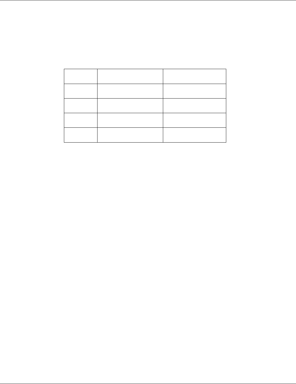
Figure 11. Multiple Block Read Operation
The block write operation uses a simple busy signaling of the write operation duration on the
DAT0 data line (see Figure 12), regardless of the number of data lines used for transferring the
data.
Figure 12. Multiple Block Write Operation
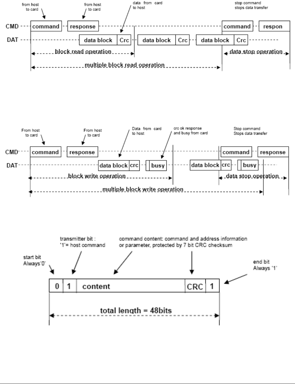
Command tokens use the coding scheme shown below:
Figure 13. Command Token Format
Each command token is preceded by a start bit and succeeded by an end bit. The total length
is 48 bits.

SLC Industrial microSD Memory Card L5ENG00392 Rev. C
© 2014 | Delkin Devices Inc. 27
Each token is protected by CRC bits so that transmission errors can be detected and operation
may be repeated. Response tokens have four coding schemes, depending on their content.
The token length is either 48 or 136 bits.
Figure 14. Response Token Format
In the CMD line, the MSB bit is transmitted first and the LSB bit is the last.
When the Wide Bus option is used, the data is transferred 4 bits at a time (see Figure 15).
Start when the end bits, as well as the CRC bits are transmitted for every one of the DAT lines.
CRC bits are calculated and checked for every DAT line individually. The CRC status response
and busy indication will be sent by the card to the host on DAT0 only. (DAT1-DAT3 during that
period are “don’t care.”)
Figure 15. Data Packet Format

SLC Industrial microSD Memory Card L5ENG00392 Rev. C
© 2014 | Delkin Devices Inc. 28
5.2 SPI Bus Protocol
While the microSD Channel is based on command and data bit streams which are initiated by
a start bit and terminated by a stop bit, the SPI channel is byte oriented.
5.2.1 Command
Every command or data block is built of 8-bit bytes and is byte aligned to the CS signal (i.e.,
the length is a multiple of 8 clock cycles).
5.2.2 Response
The response behavior in the SPI mode differs from the SD mode in the following three
aspects:
The selected card always responds to the command.
Two new (8- and 16-bit) response structures are used.
When the card encounters a data retrieval problem, it will respond with an error (which
replaces the expected data block) rather than returning a time-out, as in the SD mode.
In addition to the command response, every data block sent to the card during write operations
will be acknowledged with a special data response token.
5.2.3 Data Read
Single and multiple blocks read commands are supported in SPI mode. However, in order to
comply with the SPI industry standard, only two (unidirectional) signals are used. Upon
reception of a valid read command the card will respond with a response token followed by a
data token of the length defined in a previous SET_BLOCKLEN (CMD16) command. A multiple
block read operation is terminated, similar to the SD protocol, with the STOP_TRANSMISSION
command.
Figure 16. Read Operation
A valid data block suffixed with a 16 CRC generated by the standard CCITT polynomial
X
16
+X
12
+X
5
+1. In the case of data retrieval error, the card will not transmit any data. Instead, a
special data error token will be sent to the host. Figure 17 shows a data read operation which
terminated with an error token.

SLC Industrial microSD Memory Card L5ENG00392 Rev. C
© 2014 | Delkin Devices Inc. 29
Figure 17. Read Operation – Data Error
Single and multiple block write operations are supported in SPI mode. Upon receipt of a valid
write command, the card replies with a response token, and then waits for a data block to be
sent from the host. CRC suffix, block length, and start address restrictions are identical to the
read operation. (See Figure 17.)
Figure 18. Write Operation
After a data block has been received, the card will respond with a data-response token. If the
data block has been received without errors, it will be programmed. As long as the card is busy
programming, a continuous stream of busy tokens will be sent to the host (effectively holding
the Data Out line low).
5.3 Card Registers
Six registers are defined within the card interface: OCR, CID, CSD, RCA, DSR and SCR.
These can be accessed only by corresponding commands. The OCR, CID, CSD and SCR
registers carry the card- and content-specific information, while the RCA and DSR registers
are configuration registers, storing actual configuration parameters.
In order to enable future extension, the card shall return 0 in the reserved register bits.
5.3.1 OCR Register
The 32-bit operation conditions register stores the voltage profile of the card. Additionally, this
register includes status information bits. One status bit is set if the card power up procedure
has been finished. This register includes another status bit indicating the card capacity status
after set power up status bit. The OCR register shall be implemented by the cards.

SLC Industrial microSD Memory Card L5ENG00392 Rev. C
© 2014 | Delkin Devices Inc. 30
The 32-bit operation conditions register stores the voltage profile of the card. Bit 7 of OCR is
newly defined for Dual Voltage Card and set to 0 in default. If a Dual Voltage Card does not
receive CMD8, OCR bit 7 in the response indicates 0, and the Dual Voltage Card which
received CMD8, sets this bit to 1.
Additionally, this register includes two more status information bits.
Bit 31 — Card power up status bit. This status bit is set if the card power up procedure has
completed.
Bit 30 — Card capacity status bit. This status bit is set to 1 if the card is High Capacity
SDHC Memory Card. 0 Indicates that the card is Standard Capacity SD Memory Card. The
Card Capacity status bit is valid after the card power up procedure is completed and the
card power up status bit is set to 1. The Host shall read this status bit to identify a Standard
or High Capacity SDHC Memory Card. The OCR register shall be implemented by the
cards.

SLC Industrial microSD Memory Card L5ENG00392 Rev. C
© 2014 | Delkin Devices Inc. 31
Table 10. OCR Register Definition
OCR bit position
OCR Fields Definition
VDD
Voltage
Window
0-3
Reserved
4
Reserved
5
Reserved
6
Reserved
7
Reserved for Low Voltage Range
8
Reserved
9
Reserved
10
Reserved
11
Reserved
12
Reserved
13
Reserved
14
Reserved
15
2.7-2.8
16
2.8-2.9
17
2.9-3.0
18
3.0-3.1
19
3.1-3.2
20
3.2-3.3
21
3.3-3.4
22
3.4-3.5
23
3.5-3.6
24-29
Reserved
30
Card Capacity Status (CCS)1
31
Card power up status bit (busy)2
Notes: 1. This bit is valid only when the card power up status bit is set.
2. This bit is set to LOW if the card has not finished the power up routine.
The supported voltage range is coded as shown in Table 10. A voltage range is not supported
if the corresponding bit value is set to LOW. As long as the card is busy, the corresponding bit
(31) is set to LOW.

SLC Industrial microSD Memory Card L5ENG00392 Rev. C
© 2014 | Delkin Devices Inc. 32
5.3.2 CID Register
The Card Identification (CID) register is 128 bits wide. It contains the card identification
information used during the card identification phase. Every individual Read/Write (RW) card
shall have a unique identification number.
Table 11. CID Register Definition
Name
Field
Width
CID-slice
Manufacturer ID
MID
8
[127:120]
OEM/Application ID
OID
16
[119:104]
Product name
PNM
40
[103:64]
Product revision
PRV
8
[63:56]
Product serial number
PSN
32
[55:24]
Reserved
--
4
[23:20]
Manufacturing date
MDT
12
[19:8]
CRC7 checksum
CRC
7
[7:1]
Not used (always 1)
--
1
[0:0]
The structure of the CID register is defined as follows:
MID
An 8-bit binary number that identifies the card manufacturer. The MID number is controlled,
defined, and allocated to a SD Memory Card manufacturer by the SD-3C, LLC. This
procedure is established to ensure uniqueness of the CID register.
OID
A two-character ASCII string that identifies the card OEM and/or the card contents (when
used as a distribution media either on ROM or FLASH cards). The OID number is
controlled, defined, and allocated to an SD Memory Card manufacturer by the SD-3C, LLC.
This procedure is established to ensure uniqueness of the CID register.
Note: SD-3C, LLC licenses companies that wish to manufacture and/or sell SD Memory
Cards, including but not limited to flash memory, ROM, OTP, RAM, and SDIO Combo
Cards. The SD-3C, LLC is a limited liability company established by Matsushita Electric
Industrial Co. Ltd., SanDisk Corporation and Toshiba Corporation.
PNM
The product name is a string, five-character ASCII string.
PRV
The product revision is composed of two Binary Coded Decimal (BCD) digits, four bits
each, representing an “n.m” revision number. The “n” is the most significant nibble and “m”

SLC Industrial microSD Memory Card L5ENG00392 Rev. C
© 2014 | Delkin Devices Inc. 33
is the least significant nibble. For example, the PRV binary value field for product revision
“6.2” will be 0110 0010b.
5.3.3 CSD Register
The Card-Specific Data register provides information regarding access to card contents. The
CSD defines the data format, error correction type, maximum data access time, whether the
DSR register can be used, etc. The programmable part of the register (indicated by R, W or
W1, see Table 12 below) can be changed by CMD27.
5.3.4 CSD_STRUCTURE
Field structures of the CSD register differ, depending on the Physical Specification Version and
Card Capacity. The CSD_STRUCTURE field in the CSD register indicates its structure
version.
5.3.5 CSD Register (CSD Version 2.0)
Table 12 shows Definition of the CSD for the High Capacity SDHC Memory Card (CSD
Version 2.0). This section describes the CSD fields and the relevant data types for the High
Capacity SDHC Memory Card.
CSD Version 2.0 is applied to only the High Capacity SDHC Memory Card. The field name in
parenthesis is set to fixed value and indicates that the host is not necessary to refer these
fields. The fixed values enables host, which refers to these fields, to keep compatibility to CSD
Version 1.0. The Cell Type field is coded as follows:
R — Readable
W(1) — Writable once
W — Writable multiple times
Table 12. CSD Register Fields (Version 2.0)
Name
Field
Width
Value
Cell Type
CSD-slice
CSD structure
Reserved
CSD_STRUCTURE
-
2
6
01b
00 0000b
R
[127:126]
[125:120]
Data read access-time
(TAAC)
8
0Eh
R
[119:112]
Data read access-time in
CLK Cycles (NSAC*100)
(NSAC)
8
00h
R
[111:104]
Max. data transfer rate
(TRAN_SPEED)
8
32h or 5Ah
R
[103:96]
Card command classes
CCC
12
01x11011010
1b
R
[95:84]
Max. read data block length
(READ_BL_LEN)
4
9
R
[83:80]
Partial blocks for read
allowed
(READ_BL_PARTIAL)
1
0
R
[79:79]
Write block misalignment
(WRITE BLK
MISALIGN)
1
0
R
[78:78]
Read block misalignment
(READ_BLK_MISALI
GN)
1
0
R
[77:77]

SLC Industrial microSD Memory Card L5ENG00392 Rev. C
© 2014 | Delkin Devices Inc. 34
Name
Field
Width
Value
Cell Type
CSD-slice
DSR implemented
DSR_IMP
1
x
R
[76:76]
Reserved
-
6
00 0000b
R
[75:70]
Device size
C SIZE
22
00 xxxxh
R
[69:48]
Reserved
-
1
0
R
[47:47]
Erase single block enable
(ERASE_BLK_EN)
1
1
R
[46:46]
Erase sector size
(SECTOR_SIZE)
7
7Fh
R
[45:39]
Write protect group size
(WP_GRP_SIZE)
7
0000000b
R
[38:32]
Write protect group enable
Reserved
WP_GRP_ENABLE)
1
2
0
00b
R
[31:31]
[30:29]
Write speed factor
(R2W_FACTOR)
3
010b
R
[28:26]
Max. write data block length
(WRITE_BL_LEN)
4
9
R
[25:22]
Partial blocks for write
allowed
Reserved
(WRITE_BL_PARTIAL
-
1
5
0
00000b
R
[21:21]
[20:16]
File format group
(FILE
_FORMAT_GRP)
1
0
R
[15:15]
Copy flag (OTP)
COPY
1
x
R/W(1)
[14:14]
Permanent write protection
PERM_WRITE_PROT
ECT
1
x
R/W(1)
[13:13]
Temporary write protection
TMP_WRITE_PROTE
CT
1
x
R/W
[12:12]
File format
(FILE_FORMAT)
2
00b
R
[11:10]
Reserved
-
2
00b
R
[9:8]
CRC
CRC
7
xxxxxxxb
R/W
[7:1]
Not used, value is always 1
-
1
1
-
[0:0]
CSD register fields are defined as follows:
TAAC
This field is fixed on 0Eh, which indicates 1 ms. The host should not use TAAC, NSAC, and
R2W_FACTOR to calculate timeout, and should use fixed timeout values for read and write
operations.
NSAC
This field is fixed to 00h. NSAC should not be used to calculate time-out values.
TRAN_SPEED
Definition of this field is same as in CSD Version1.0.
CCC
Definition of this field is same as in CSD Version1.0.
READ_BL_LEN
This field is fixed to 9h, which indicates READ_BL_LEN=512 Byte.

SLC Industrial microSD Memory Card L5ENG00392 Rev. C
© 2014 | Delkin Devices Inc. 35
READ_BL_PARTIAL
This field is fixed to 0, which indicates partial block read is inhibited and only unit of block
access is allowed.
WRITE _BLK_MISALIGN
This field is fixed to 0, which indicates write access crossing physical block boundaries is
always disabled in High Capacity SDHC Memory Cards.
READ_BLK_MISALIGN
This field is fixed to 0, which indicates read access crossing physical block boundaries is
always disabled in High Capacity SDHC Memory Cards.
DSR_IMP
Definition of this field is same as in CSD Version 1.0.
C_SIZE
This field is expanded to 22 bits and can indicate up to 2TB. This is the same as the
maximum memory space specified by a 32-bit block address.
This parameter is used to calculate the user data area capacity in the SD Memory Card
(not include the protected area). The user data area capacity is calculated from C_SIZE as
follows:
Memory capacity = (C_SIZE+1) x 512K bytes.
As the maximum capacity of the Physical Layer Specification, Version 2.00 is 32GB; the
upper six bits of this field shall be set to 0.
ERASE_BLK_EN
This field is fixed to 1, which means the host can erase one or multiple units of 512 bytes.
SECTOR_SIZE
This field is fixed to 7Fh, which indicates 64K bytes. This value does not relate to the erase
operation. Version 2.00 cards indicate memory boundaries by AU size and this field should
not be used.
WP_GRP_SIZE
This field is fixed to 00h. The High Capacity SDHC Memory Card does not support write
protected groups.
WP_GRP_ENABLE
This field is fixed to 0. The High Capacity SDHC Memory Card does not support write
protected groups.
R2W_FACTOR
This field is fixed to 2h, which indicates 4 multiples. Write timeout can be calculated by
multiplying the read access time and R2W_FACTOR. However, the host should not use
this factor and should use 250 ms for write timeout.

SLC Industrial microSD Memory Card L5ENG00392 Rev. C
© 2014 | Delkin Devices Inc. 36
WRITE_BL_LEN
This field is fixed to 9h, which indicates WRITE_BL_LEN=512 bytes.
WRITE_BL_PARTIAL
This field is fixed to 0, which indicates partial block read is inhibited and only unit of block
access is allowed.
FILE_FORMAT_GRP
This field is set to 0. Host should not use this field.
COPY
Definition of this field is same as in CSD Version 1.0.
PERM_WRITE_PROTECT
Definition of this field is same as in CSD Version 1.0.
TMP_WRITE_PROTECT
Definition of this field is same as in CSD Version 1.0.
FILE_FORMAT
This field is set to 0. Host should not use this field.
CRC
Definition of this field is same as in CSD Version1.0.
RCA Register
The writable 16-bit relative card address register carries the card address that is published
by the card during the card identification. This address is used for the addressed host-card
communication after the card identification procedure. The default value of the RCA
register is 0x0000. The value 0x0000 is reserved to set all cards into the Stand-by State
with CMD7.
DSR Register (Optional)
The 16-bit Driver Stage Register can be used to improve the bus performance for extended
operating conditions (depending on parameters like bus length, transfer rate, or number of
cards). The CSD register carries the information about the DSR register usage. The default
value of the DSR register is 0x404.
SCR Register
In addition to the CSD register, there is another configuration register named SD CARD
Configuration Register (SCR). SCR provides information on the SD Memory Card's special
features that were configured into the given card. The size of SCR register is 64 bits. This
register shall be set in the factory by the SD Memory Card manufacturer.
Table 13 describes the SCR register content.

SLC Industrial microSD Memory Card L5ENG00392 Rev. C
© 2014 | Delkin Devices Inc. 37
Table 13. SCR Fields
Description
Field
Width
Cell
Type
SCR
Slice
SCR Structure
SCR_STRUCTURE
4
R
[63:60]
SD Memory Card –
Spec. Version
SD_SPEC
4
R
[59:56]
Data_status_after erases
DATA_STAT_AFTER_ERASE
1
R
[55:55]
SD Security Support
SD_SECURITY
3
R
[54:52]
DAT Bus widths
supported
SD_BUS_WIDTHS
4
R
[51:48]
Reserved
-
16
R
[47:32]
Reserved for
manufacturer usage
-
32
R
[31:0]
Table 14. SCR Register Structure Versions
SCR_STRUCTURE
SCR Structure Version
SD Physical Layer Spec Version
D
SCR Version 1.0
Version 1.01 - 2.00
1-15
Reserved
SD_SPEC
Describes the Physical Layer Specification Version supported by the card.
Table 15. Physical Layer Specification Version
SD_SPEC
Physical Layer Specification Version Number
0
Version 1.0-1.01
1
Version 1.10
2
Version 2.00
3-15
Reserved
DATA_STAT_AFTER_ERASE
Defines the data status after erase, whether it is 0 or 1, the status is card vendor
dependent.
SD_SECURITY
Describes the Security Specification Version supported by the card.

SLC Industrial microSD Memory Card L5ENG00392 Rev. C
© 2014 | Delkin Devices Inc. 38
Table 16. SD-supported Security Algorithm
SD_SECURITY
Security Specification Version
0
No security
1
Not used
2
Version 1.01
3
Version 2.00
4-7
Reserved
Note that it is mandatory for a writable SD Memory Card to support Security Protocol. For
ROM and OTP types of the SD Memory Card, this security feature is optional. In the case
of the Standard Capacity SD Memory Card Version 1.01, this field shall be set to 2. For the
High Capacity SDHC Memory Card, this field shall be set to 3.
SD_BUS_WIDTHS
The following table describes all of the DAT bus widths that are supported by this card.
Table 17. SD Memory Card Supported Bus Widths
SD_BUS_WIDTHS
Supported Bus Widths
Bit 0
1 bit (DAT0)
Bit 1
Reserved
Bit 2
4 bit (DAT0-3)
Bit 3
Reserved
Since the SD Memory Card supports at least the two bus modes 1-bit or 4-bit width, then
any SD card shall set at least bits 0 and 2 (SD_BUS_WIDTH=0101).
