
The Periodic Table of Forms with Fusion 360
1
CP11304
The Periodic Table of Forms with Fusion 360
Mike Aubry – Evangelist
Autodesk
Mike Prom – Product Manager
Autodesk
Learning Objectives
Explore how modeling workflows impact design aesthetics
Discover a methodology to deliberately craft the perception of a design
Discover Fusion 360’s software approach to different advanced modeling techniques
Challenge the way you approach design exploration
Description
“Why does design so often struggle to communicate its value to the world when it's something we all
recognize?” This was the question posed by Gray Holland, renowned founder of Alchemy Labs, 6 years
ago when he developed the now famous Periodic Table of Forms, a table that explains how surface
curves change the perception of a design. Designs have a feel. The sharp edges of a B-52 Bomber look
menacing, while the curves of the VW Bug look friendly. In this hands-on workshop we will explore how
Fusion 360 software unlocks these formative design types. We will explore the structure of Holland’s
table and discover how to create different curvature setups. Whether you’re a new student of design
and have no idea what a G0 curve is or you’re a veteran designer looking to learn new ways to adapt
your portfolio, this class sets out to inspire you to push the boundaries of design and provide you with
tangible Fusion 360 software tactics to do it.
Special thanks to Gray for letting us showcase his compelling and useful article!
Article Source: http://www.core77.com/posts/12752/a-periodic-table-of-form-the-secret-language-of-surface-and-meaning-in-product-design-by-gray-holland-12752

The Periodic Table of Forms with Fusion 360
2
Your AU Experts
Mike Aubry is always pursuing better, faster and exciting ways to design. During the ten years he’s
worked in the computer aided design field, he’s been privileged to work with 100s of customers who do
everything from craftsman eyewear to giant fighting robots. He has professional experience in the bio-
medical, wind energy, and computational fluid dynamics simulation industries. Mike is passionate about
hackathons, and he loves working with anyone and everyone inspired to solve interesting problems. He
proudly works as an Evangelist for Autodesk Fusion 360 – a 3D CAD/CAM tool that strives to aggregate
the product development process into a single cloud based tool. He has a mechanical engineering degree
from the University of Portland.
Mike Prom is the modeling Product Manager for the Fusion 360 team. Over the years he has worked for
industrial equipment companies like Case New Holland, Bobcat and Arctic Cat. He also designed medical
beds for Tri W-G and was one of the first employees of a startup making motorized ice fishing houses.
Mike enjoys designing custom furniture, working on cars and mountain biking. He received his degree for
mechanical engineering from North Dakota State University.
Introduction
Great Design Matters Now More Than Ever
Too often we settle in our designs, focusing instead on things like cost and manufacturability. It boxes
us into design compromises and commits us to long design cycles that stagnate our brands.
What if we told you that all of this is rapidly changing?
Today’s manufacturing environment is in the midst of a dramatic transition. Additive manufacturing
techniques (aka 3D printing) continue to improve and decrease in cost. Subtractive fabrication processes
(aka CNC machining) continue to become more cost effective and readily available. We are quickly
moving towards a world where products that previously required overseas fabrication runs of several
units will be more cost effective and more desirable if they are manufactured locally and on-demand.
How will this affect “great design”? This manufacturing renaissance will be the catalyst to spur
vocational innovation. In the zero limits, on-demand manufacturing societies of the future, designers
who provide profound insight into the usage and form requirements of their customers will be
profoundly rewarded. Those who do not will atrophy, much like the paper draftsmen of the 90s, and be
relegated to tasks not yet automated.
It is critical to make sure we as designers provide to our customers the exact functionality and form they
specify. Never before has the need to apply and move quickly between different modeling techniques
been so imperative. Too often a modeling technique available to a designer is the one they are chained
to. No more. The future demands a product design platform built to evolve and adapt quickly as these
macro disruptive changes unfold.
This is where Fusion 360 comes in. Fusion 360 has a broad set of modeling tools that allow us to create
every single one of the shapes in the periodic table of forms. In this class we will go through three step-
by-step exercises that increase in modeling complexity and will allow us to utilize three different

The Periodic Table of Forms with Fusion 360
3
modeling environments available within Fusion 360: Solid modeling, sculpting, and patch (“surface”)
modeling. Employing these techniques with an attention to the design impact they have will help us as
designers prepare for this next industrial revolution and capitalize upon all of the exciting changes
ahead.
Gray Holland’s “Periodic Table of Forms”
Six years ago Gray Holland, renowned founder of Alchemy Labs, published a paper that sought to
communicate more explicitly how surface curves change the perception of a design. Designs have a feel.
The sharp edges of the 15ft tall Megabot in Figure 1 look menacing, while the curves of the new Star
Wars BB8 droid in Figure 2 look friendly:
FIGURE 1 MEGABOT FIGURE 2 BB8 DROID
FIGURE 1 IMAGE CREDIT: https://www.instagram.com/p/2ywIVYnX2g/
FIGURE 2 IMAGE CREDIT: https://fusion360.autodesk.com/projects/bb-8
These curves and edges are called “transitions,” and they are described by their continuity designation:
“Positional,” “Tangential,” or “Curvature.” Positional continuity (Referenced as “C0,” “Curvature 0,”
“G0,” or “Gaussian 0”) describes the hard edge formed when two surfaces intersect. Tangential
continuity (Referenced as “C1” or “G1”) is defined by creating a circular arc transition between the two
surfaces where the arc aligns with classic geometric tangency at both ends. C1 surfaces are smooth but
have visible break where the transitional curve ends and the attached surfaces begin. Curvature
continuity (“C2” or “G2”) is achieved when this rate of curvature transition is controlled such that it is
not discernable where one surface ends and the other begins.
The differences in each transition can be well shown using the curvature analysis tools within Fusion
360. In Figure 3, a Curvature Comb is used to show the rate of curvature transition on equal sized cubes
where one uses a chamfer, one uses a C1 fillet, and one uses a C2 fillet. Notice how the C1 example has
an abrupt curvature transition whereas the C2 transition is more gradual.

The Periodic Table of Forms with Fusion 360
4
FIGURE 3 - TRANSITION EXAMPLES SHOWN USING A CURVATURE COMB
This transition affects how light refracts off the object and how the observer experiences it. In Figure 4,
a set of Zebra Stripes (straight black and white lines) are projected onto the cubes:
FIGURE 4 - TRANSITION EXAMPLES SHOWN USING ZEBRA STRIPES
Notice how the different curvature examples reflect the stripes. The stripes transition abruptly in the C1
and the stripes transition smoothly in the C2 example.
When we blend these curves, complex layers and tones start to emerge. Take a look at the full Table of
Forms in Figure 4. Observe how simply changing edges and rounds changes how a design impacts the
viewer:

The Periodic Table of Forms with Fusion 360
5
FIGURE 4: GRAY HOLLAND’S PERIODIC TABLE OF FORMS
IMAGE CREDIT: HTTP://WWW.CORE77.COM/POSTS/12752/A-PERIODIC-TABLE-OF-FORM-THE-SECRET-LANGUAGE-OF-SURFACE-AND-MEANING-IN-PRODUCT-
DESIGN-BY-GRAY-HOLLAND-12752
Some of these models, like the C0 form in Figure 5, are fairly straight forward to create. Others such as
the C1~2~0 shown in Figure 6 require more attention and technique:
FIGURE 5: C0 FIGURE 6: C~1~2~0
Most physical designs provide clear parameters to build around. Generous rounds must be added to
areas that experience structural loading. Tight edges must be maintained in areas of critical fit. Sharp
edges are to be avoided where handling is involved.
Interestingly, nowhere in the Table of Forms is there any reference to what the form actually does!
Without explicitly knowing what this form is used for, the value (aka its purpose) is left to the viewer to

The Periodic Table of Forms with Fusion 360
6
infer. Certain forms just “look” stronger, rougher, softer, sleeker, or more elegant. As designers we can
use the assumptions people make based on form shapes to take functional designs and turn them into
great designs. Great design is achieved when a product not only accomplishes its engineered function
but also fully communicates its purpose and sets an emotional tone befitting of its brand.
In the next three exercises you will go step by step through creating a C1 form, C2~0 form, and a C1~2~0
as shown in Figure 7.
FIGURE 7: EXERCISE EXAMPLES PREVIEW – C1, C2~0, & C1~2~0
These three forms were chosen because they showcase a variety of modeling techniques that achieve a
variety of different design tones and emotions. Learning and applying these different foundational
techniques to your designs will allow you to capture exactly the functionality and character you are
looking for in your designs.
Let’s get started.
Exercise 1 – Creating a C1 Form
Dependable. Familiar. Strong.
The C1 form is perhaps the most common of forms applied today. It is a very functional form that
employs simple to machine edges and rounds that remove sharpness. In typical cases it is easy to model
in CAD. The C1’s attainability has made it a staple of traditional mechanical CAD tools like Autodesk
Inventor and SolidWorks for years. As shown in Figure 8, designs that deliberately employ it evoke tones
of familiarly and dependability. For example, most power tools like the Dewalt drill shown in Figure 9
opt to use the well-defined lines found in the C1:
FIGURE 8: C1 FORM FIGURE 9: DEWALT COMPACT HAMMER DRILL
Image Credit: http://www.dewalt.com/tools/cordless-drills-hammerdrills-dcd785c2.aspx

The Periodic Table of Forms with Fusion 360
7
In this exercise you will explore how Autodesk Fusion 360 employs the C1 technique using parametric
modeling functionality:
Exercise 1 – C1 Form Creation
1. Open the file “AU Start C1.f3d”
2. In the browser, make sure the visibility for Sketch1 and Sketch2 is on:
3. Press “E” to open the Extrude dialogue box. Select the profiles contained in Sketch1 as
shown. Change the Extrude Direction to be Symmetric. Enter an extrusion distance of
0.25:
4. Select the profiles as shown in Sketch 2. Choose a distance of 0.25. Make certain
Operation is set to “Join” and Direction is “Symmetric.”

The Periodic Table of Forms with Fusion 360
8
5. Press the F key to open the Fillet dialogue box. Select the four edges where the round
cylinders connect to the square cylinder. Chose a radius of 0.25
6. Create a fillet around the edge boarder that has a radius of 0.0625
7. End of Exercise 1.
Exercise 2 – Creating a C2~0 Form
Precise. Sleek. Aggressive.
The C2~0 form represents a blending of refinement with pragmatism. A pure C2 form maintains
complete smoothness throughout but can dull a design’s impact by glossing over key definitions. A
purely C0 form is very exact, but its oblong edges often finish crude and unrefined.

The Periodic Table of Forms with Fusion 360
9
The C2~0, as shown in Figure 10, combines these two forms so it maintains its rigidity while providing
sleek refinement through areas of transition. The F22, shown in Figure 11, is a great example of the
C2~0:
FIGURE 10: C2~0 FORM FIGURE 11: F22 RAPTOR
FIGURE 11 IMAGE CREDIT: 7-themes.com/data_images/out/61/6980090-f22-raptor.jpg
In this exercise you will explore how Autodesk Fusion 360 employs the C2~0 technique using sculpting
combined with solid modeling functionality:
Exercise 2 – Creating a C2~0 Form
1. Open the file “AU Start C2-0.f3d” In the Browser, make sure Sketch1 and Sketch2 are
visible:
2. Select Create Form
3. Select Create/Sphere. Create two spheres of diameter 1, longitude 6, and latitude 6.
Choose the starting points to be at the center points of both circles. Make one sphere
oriented vertically and one sphere oriented horizontally:

The Periodic Table of Forms with Fusion 360
10
4. Double click on the sphere body to select:
5. Right Click to select Move. Rotate the body 30 degrees to align the misaligned sphere’s
faces with the blue origin’s axis:
The final spheres should be aligned like this:
6. Use the shift key and left click to select the top faces of the sphere. Right click and
select edit form:

The Periodic Table of Forms with Fusion 360
11
7. Use the manipulator to slightly shrink the faces as shown:
8. Select Create/Flatten. Choose the Points on top of the sphere as shown and complete
the flattening operation. Tip-go to a side view and drag select:
9. Make sure the sketches are still on and edit the selected faces one more time, dragging
them until they are parallel with the line in the sketch:

The Periodic Table of Forms with Fusion 360
12
10. Repeat the prior two steps on the remaining sphere:
11. From the side view select the bottom halves of the two spheres:
12. Right click and Delete the faces as shown:
13. Repeat steps 10 and 11 from the top view so that you are left with a quarter of each
sphere. The result should look like what you see in step 13.

The Periodic Table of Forms with Fusion 360
13
14. Select Create/Bridge. Choose the faces on the left as Side 1 and the faces to the right as
Side 2.
15. Select Mirror Duplicate. Choose the shown plane to mirror and create symettry on the
body:
16. Repeat the prior step and use the plane as shown:

The Periodic Table of Forms with Fusion 360
14
17. Use shift and the left mouse button to select the faces shown. Right click and select
Delete:
18. Repeat the above deletion step on the remaining unjoined faces as well:
19. Double click the edge of the open profile. Right Click and select Fill Hole:

The Periodic Table of Forms with Fusion 360
15
20. Use Fill Hole on the remaining hole:
21. Select Modify/Crease. Crease the edges as shown:
22. Repeat the crease command and crease the edges shown below as well:

The Periodic Table of Forms with Fusion 360
16
23. Use Edit form to modify the geometry to resemble the shape as shown. Moving the
inner circle so that it looks concentric with the outside edge:
24. Select Finish Form
25. The next thing to do is create the holes. Expand the bodies folder in the browser and
turn off the visibility of the body:

The Periodic Table of Forms with Fusion 360
17
26. Under the create pull down select extrude, enter .175 for the distance:
27. Create a sketch on the top of the new cylinder that was created, under sketch select
Project Geometry and select the top circle:

The Periodic Table of Forms with Fusion 360
18
28. Turn on the visibility for all solid bodies.
29. Select Offset Plane. Choose the plane as shown. Create an offset plane of distance 0.3
30. Hold down the left mouse button over the newly created plane. A list of selectiable
options will appear. Select the workplane:
31. Right click and choose New Sketch.
32. Turn on the visibilty of Sketch1:

The Periodic Table of Forms with Fusion 360
19
33. Project the Skecth Circle and Geometric Point onto the sketch.
34. Add arcs to complete the profile as shown below. These are found under Sketch/Arc/3
Point Arc. Use the natrual edge boarders to align the arcs:

The Periodic Table of Forms with Fusion 360
20
35. Select Create/Loft. Select the shown profiles. Set the Operation to New Body:
36. Turn off the visibility of main body again, leaving just the bodies in the image below:

The Periodic Table of Forms with Fusion 360
21
37. Select Pattern/Mirror. Mirror the the visible body. Set pattern type to Body. Choose the
Body 14 as the Object. Choose the shown face as the Mirror Plane:
38. Repeat the mirror selection. Mirror both bodies on the shown mirror plane:

The Periodic Table of Forms with Fusion 360
22
39. Select the Move command. Select the two newly mirrored bodies. Set Pivot to the
Origin. Check done.
40. Rotate the bodies 90 degrees as shown:
41. Turn back on the visiblity of the main body.

The Periodic Table of Forms with Fusion 360
23
42. Select Combine. Choose Body 13 as the Target. Choose all other remaining bodies as
the Tool Bodies. Set the operation to Cut.
43. Select Fillet. Create 0.05 G2 fillets on the edges as shown:
44. End of Exercise 2

The Periodic Table of Forms with Fusion 360
24
Exercise 3 – Creating a C1~2~0 Form
Robust. Balanced. Expensive.
The C1~2~0 form often represents the next level in high end design. The intricacy and varied nature of
how its curves blend require attuned eyes and attention to structural necessity. The difference between
an exceptional design and one that overreaches is subtle. The addition of a well-placed smooth element
or sharp transition can make the difference between a $40k car shown in Figure 12 and a $70k car
shown in Figure 13:
FIGURE 12: 2012 VOLVO XC90 FIGURE 13: 2016 VOLVO XC90
Figure 13 Image Credit: http://media.caranddriver.com/images/media/601419/2016-volvo-xc90-interior-photo-601421-s-986x603.jpg
The C1~2~0 form is elegant and crisp. As shown in Figure 14, it uses the soft, organic shapes of C2, sharp
cuts from C0 and rounded edges from C1. This form communicates that the design is expensive while
showing that it is refined. When looking at this form it is inviting to touch. Notice the 2014 Apple
Macbook Pro in Figure 15. There is a “feeling” that you get when you pick it up and hold it in your hands
that comes from the subtle curvature and attention to finishing details which makes it stand out:
FIGURE 14: C1~2~0 FORM FIGURE 15: MACBOOK PRO
Figure 15 Image Credit: http://www.apple.com/macbook-air/

The Periodic Table of Forms with Fusion 360
25
In this exercise you will explore how Autodesk Fusion 360 employs the C1~2~0 technique using sculpting
combined with patch (surface) modeling functionality:
Exercise 3 – Creating a C1~2~0 Form
1. Open the file “AU Start C1-2-0.f3d.” In the Browser make sure Sketch1 and Sketch2 are
visible:
2. Select create Form:
3. Select Create/Quadball. Pick the top origin plane.

The Periodic Table of Forms with Fusion 360
26
4. Use the sketch point Center. Use a Diameter of 1. Span Faces of 2.
5. Repeat on the other circle.

The Periodic Table of Forms with Fusion 360
27
6. Use Symmetry/Mirror-Internal to create symmetry on the two quadballs by clicking on
the faces as shown:
7. Repeat for the second sphere.

The Periodic Table of Forms with Fusion 360
28
8. Apply the symmetry to the top and bottom, along with the right and left side.
9. Repeat for the other sphere.
10. Select Modify/Edit Form. Use Command (Mac) / CTRL (PC) to select the top four sections
of the left quad as shown. Use the manipulator to move -0.1 downward:

The Periodic Table of Forms with Fusion 360
29
11. Repeat Edit Form as shown for the other sphere:
12. Select Modify/Bridge the bridge command from the modify pull down. For Side One
choose the 4 faces on the left sphere as shown. For Side Two choose the four faces on
the right sphere:
13. The Bridge should look like this:
14. Use Edit Form to modify the center of the body. As shown, select two edges on each
side of the center. Drag the manipulator towards the center a distance of 0.08. This will

The Periodic Table of Forms with Fusion 360
30
produce a pinched effect and make the form look more like the original sketch profile:
15. Use Edit Form to flatten the center of what previously was the left quadball. Select the
point shown below and move the vertical arrow down towards the center -0.3:
16. Use Edit Form to move the point shown below down -0.05:

The Periodic Table of Forms with Fusion 360
31
17. Select Inspect/Zebra Analysis. Choose the body to activate the zebra stripes. Change
the Direction to Horizontal.
18. In the next few steps these stripes will assist in creating consistent continuity across the
part. The wavy zebra stripes shown below need to be horizontal such that cuts done in
later steps will be constantly applied across the surface and will not result in irregular
waves:
19. Select Edit Form. Choose the edge as shown below. Alter the Planar Scale to 0.6 as
shown:
The Periodic Table of Forms with Fusion 360
32
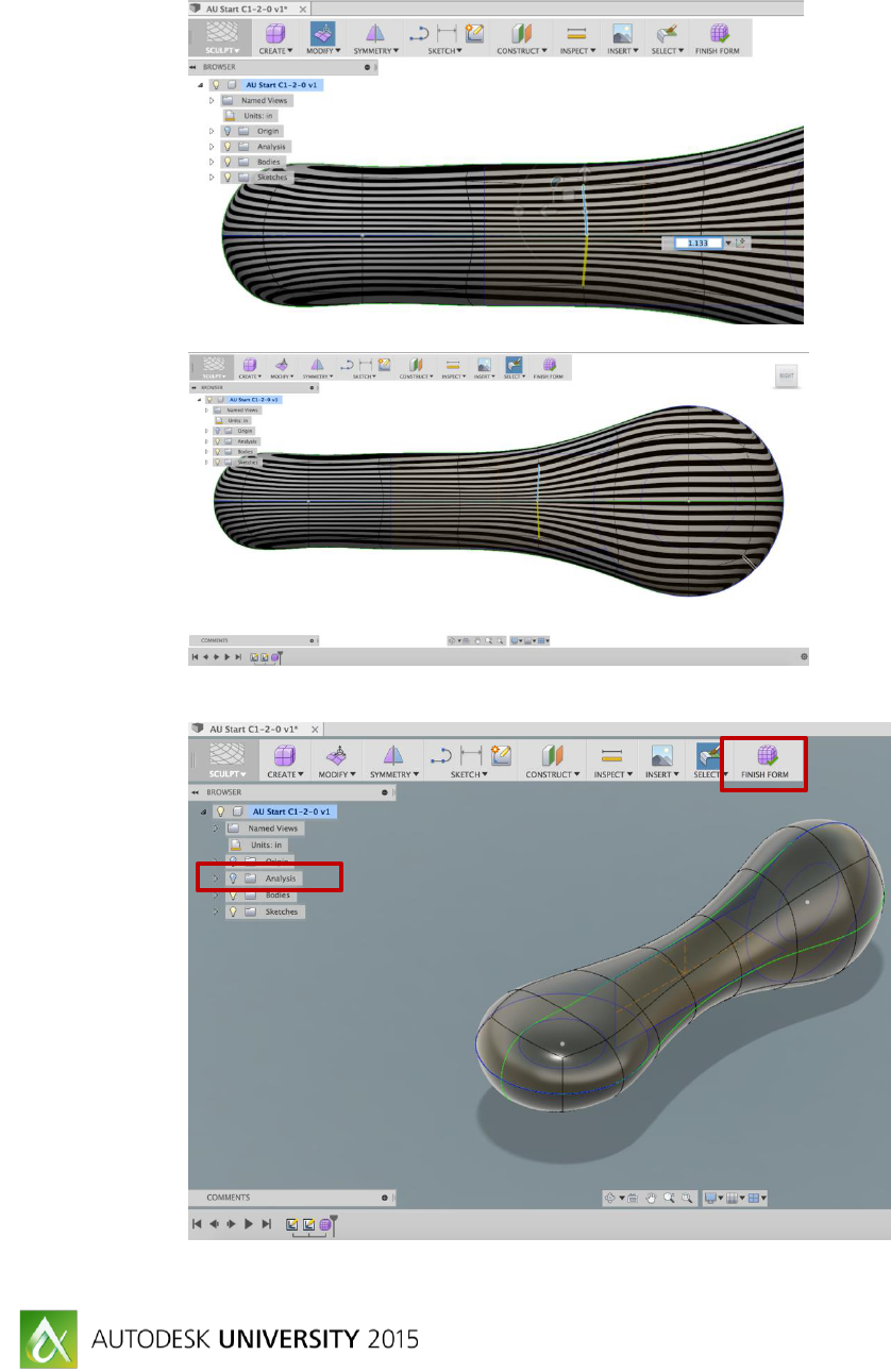
20. Use Edit Form to alter the Planar Scale of the edge shown below to 1.133:
21. Repeat Edit Form to alter the Planar Scale of the edge to 1.133 shown below:
Note the change in the stripe continuity.
22. Turn off Zebra Analysis by clicking the light bulb in the browser and select Finish Form:

The Periodic Table of Forms with Fusion 360
33
23. Activate the Patch Environment. This is the environment that will be used to create the
C0 edges:
24. Turn off the visibility of Bodies and turn on the visibility of all Sketches:
25. As shown, extrude the selected profiles a distance of 1 and set Direction to Symmetric:

The Periodic Table of Forms with Fusion 360
34
26. To see the extruded surfaces turn on the visibility of the Bodies folder, Body4 and
Body5. Turn off Visibility of Body3:
27. As shown, extrude the selected profiles a distance of 1 and set Direction to Symmetric:
28. Turn on the visibility of Body3.

The Periodic Table of Forms with Fusion 360
35
29. Select the Create/Boundary Fill. For Select Tools choose the five bodies available in the
Bodies Folder:
30. For Select Cells choose the box shown and set Operation to New Component:
31. Turn off the visibility of the Bodies Folder. Component1 will remain shown:

The Periodic Table of Forms with Fusion 360
36
32. Change Workspace to Model:
33. Add a 0.025 G2 fillet to the top and bottom edge of the circle that was cut in the image
as shown:
34. End of Exercise.
