
Rockwell Automation Publication BATCH-UM004C-EN--D - November 2023
Supersedes Publication# BATCH-UM004B-EN-D - May 2022
User Manual
Original Instructions
FactoryTalk Batch
Equipment Editor User
Manual

FactoryTalk Batch Equipment Editor User Manual
2 Rockwell Automation Publication BATCH-UM004C-EN--D - November 2023
Important User Information
Read this document and the documents listed in the additional resources section about installation, configuration, and
operation of this equipment before you install, configure, operate, or maintain this product. Users are required to
familiarize themselves with installation and wiring instructions in addition to requirements of all applicable codes, laws,
and standards.
Activities including installation, adjustments, putting into service, use, assembly, disassembly, and maintenance are
required to be carried out by suitably trained personnel in accordance with applicable code of practice.
If this equipment is used in a manner not specified by the manufacturer, the protection provided by the equipment may
be impaired.
In no event will Rockwell Automation, Inc. be responsible or liable for indirect or consequential damages resulting from
the use or application of this equipment.
The examples and diagrams in this manual are included solely for illustrative purposes. Because of the many variables
and requirements associated with any particular installation, Rockwell Automation, Inc. cannot assume responsibility or
liability for actual use based on the examples and diagrams.
No patent liability is assumed by Rockwell Automation, Inc. with respect to use of information, circuits, equipment, or
software described in this manual.
Reproduction of the contents of this manual, in whole or in part, without written permission of Rockwell Automation, Inc.,
is prohibited.
Throughout this manual, when necessary, we use notes to make you aware of safety considerations.
WARNING:
Identifies information about practices or circumstances that can cause an explosion in a hazardous environment, which may lead to
personal injury or death, property damage, or economic loss.
ATTENTION:
Identifies information about practices or circumstances that can lead to personal injury or death, property damage, or economic loss.
Attentions help you identify a hazard, avoid a hazard, and recognize the consequence.
IMPORTANT
Identifies information that is critical for successful application and understanding of the product.
Labels may also be on or inside the equipment to provide specific precautions.
SHOCK HAZARD: Labels may be on or inside the equipment, for example, a drive or motor, to alert people that dangerous voltage may be present.
BURN HAZARD:
Labels may be on or inside the equipment, for example, a drive or motor, to alert people that surfaces may reach dangerous
temperatures.
ARC FLASH HAZARD: Labels may be on or inside the equipment, for example, a motor control center, to alert people to potential Arc Flash. Arc Flash will
cause severe injury or death. Wear proper Personal Protective Equipment (PPE). Follow ALL Regulatory requirements for safe work practices and for
Personal Protective Equipment (PPE).
Rockwell Automation recognizes that some of the terms that are currently used in our industry and in this publication are
not in alignment with the movement toward inclusive language in technology. We are proactively collaborating with
industry peers to find alternatives to such terms and making changes to our products and content. Please excuse the
use of such terms in our content while we implement these changes.

Rockwell Automation Publication BATCH-UM004C-EN--D - November 2023 3
Summary of changes in Equipment Editor
This publication contains the following new or updated information. This
list includes substantive updates only and is not intended to reflect all
changes. The identified change will fall into one of these categories:
• New feature
• Enhanced feature
• Functional change
• Anomaly fix
• Usability improvement
• Clarification
Topic
Reason for change
Area models on page 23
Enhanced feature
Material capability removal on page 27
New feature
Create Phase Class dialog box - General tab on page 139
Enhanced feature
Edit Phase dialog box - General tab on page 163
Enhanced feature
Edit Operation Sequence dialog box - General tab on page
190
Enhanced feature

Rockwell Automation Publication BATCH-UM004C-EN--D - November 2023 5
Table of Contents
About the Equipment Editor manual ........................................... 13
Legal Notices .............................................................................. 13
Additional resources ................................................................... 14
Chapter 1
FactoryTalk Batch Equipment Editor security ............................. 18
Open FactoryTalk Batch Equipment Editor ............................ 18
FactoryTalk Batch Equipment Editor interface ............................ 19
Menu bar ............................................................................... 20
Toolbar .................................................................................. 20
Chapter 2
Create an area model ................................................................. 24
Open an area model ................................................................... 25
Area models migration .......................................................... 26
Area models and FactoryTalk Batch Material Manager ........ 26
Material database changes .............................................. 26
Material database is unavailable ..................................... 27
Material capability removal .............................................. 27
Verify and deploy area model ..................................................... 28
Chapter 3
XML area models ........................................................................ 31
Import an XML area model ..................................................... 31
Import enumerations ........................................................ 32
Import system phase classes .......................................... 33
Export an area model to XML ............................................... 34
Convert XML to binary from command line ........................... 34
Chapter 4
System enumeration sets ........................................................... 37
Create enumeration sets ............................................................. 38
Add enumeration members ................................................... 39
Edit enumerations and sets ........................................................ 40
Delete enumerations and sets .............................................. 40
Chapter 5
Parameters and reports in recipes .............................................. 43
Parameters example .............................................................. 43
Parameters, reports, and phase tags .......................................... 44
Overview of tags for phases .................................................. 44
Phase tags ............................................................................ 45
Batch parameters and reports .................................................... 46
Phase class parameters ........................................................ 46
Phase class reports............................................................... 46
Material parameters ................................................................... 47
Types of containers ............................................................... 47
Summary of changes in
Equipment Editor
Preface
FactoryTalk Batch Equipment
Editor
Area models
Import and export area models
Enumerations overview
Parameters and reports with
FactoryTalk Batch

Table of Contents
6 Rockwell Automation Publication BATCH-UM004C-EN--D - November 2023
Default material parameters .................................................. 47
Scale parameters ....................................................................... 48
Verification method for parameter deviations ............................. 49
Control strategies overview ........................................................ 49
Control strategies example ................................................... 49
Implement control strategies ................................................. 50
Parameter and report subsets .................................................... 51
Phase class with different subsets ........................................ 51
Download parameter requests .............................................. 52
Upload report requests .......................................................... 53
Automatic Upload/Download ...................................................... 53
Control strategy with parameter subset ...................................... 54
Chapter 6
Types of electronic signatures .................................................... 57
How electronic signatures work .................................................. 57
Signature template ..................................................................... 61
Edit signature templates dialog box ...................................... 61
Add a signature template ...................................................... 62
Set signature template signoffs ............................................. 63
Set security permissions for a signoff .............................. 65
Remove signoff permissions ............................................ 67
Delete a signature template .................................................. 67
Modify a signature template .................................................. 68
Command verification policies .................................................... 69
Add electronic signatures to commands ............................... 69
Edit command verification policies ................................... 70
Change a command verification policy.................................. 70
Remove signature requirement commands .......................... 70
Chapter 7
Recipe approval tasks ................................................................. 73
Configure recipe approval steps ................................................. 74
Recipe Approvals Configuration settings ............................... 76
Edit a recipe approval ................................................................. 77
Disable recipe approval .............................................................. 77
Chapter 8
Security authority configuration ................................................... 79
Secure an area model ................................................................. 80
Chapter 9
Area model data servers ............................................................. 83
Data Servers dialog box ......................................................... 84
Edit a data server .................................................................. 84
Delete a data server .............................................................. 85
Assign data servers............................................................... 86
OPC data servers ....................................................................... 86
Electronic signatures
Recipe approval process
overview
Security authority overview
Data servers overview

Table of Contents
Rockwell Automation Publication BATCH-UM004C-EN--D - November 2023 7
Add an OPC data server ....................................................... 87
FactoryTalk Linx FactoryTalk Live Data server .......................... 88
Add a data server .................................................................. 88
FactoryTalk Linx server path ................................................. 90
Configure the FactoryTalk Linx server path .......................... 90
Logix5000 CIP data server ......................................................... 91
Add a Logix5000 CIP data server ......................................... 91
Edit a Logix5000 CIP data server ......................................... 92
Assign a Logix5000 CIP data server to a phase or sequence
.............................................................................................. 93
Chapter 10
Manage Diagnostics page system elements ............................... 95
Define shared resources ............................................................. 96
Set general information for resources ................................... 96
Configure arbitration information ........................................... 97
Set cross invocation information ........................................... 98
Configure hyperlink information ............................................ 98
Chapter 11
Unit binding expression builder ................................................... 99
Expression operators ........................................................... 100
Supported data types .......................................................... 101
Operands .................................................................................. 102
Expression validation .......................................................... 102
Create global binding requirements .......................................... 102
Edit binding requirements ................................................... 103
Delete binding requirements ............................................... 104
Chapter 12
Create a process cell class ....................................................... 105
Edit a process cell class ............................................................ 105
Create process cell instances ................................................... 106
Configure a process cell instance ....................................... 106
Set general data for a process cell ...................................... 107
General tab of Edit process cell ..................................... 107
Set arbitration data for process cell ..................................... 107
Arbitration tab of Edit Process Cell ................................ 108
Set cross invocation data for process cell ........................... 108
Cross Invocation tab properties ..................................... 109
Configure hyperlink data for a process cell ......................... 109
Edit process cell dialog box - Hyperlink tab ................... 110
Remove a process cell instance ......................................... 110
Verify icon paths ....................................................................... 111
Unique icons ............................................................................. 111
Chapter 13
Create a unit class .................................................................... 113
Resources overview
Global binding requirements
Process cell overview
Unit overview

Table of Contents
8 Rockwell Automation Publication BATCH-UM004C-EN--D - November 2023
Edit a unit class ........................................................................ 114
Create a unit instance .............................................................. 115
Unit instance configuration ....................................................... 115
Open the Edit Unit dialog box ............................................. 115
Configure the general data for a unit ................................... 116
Edit Unit dialog box - General tab .................................. 116
Configure unit attribute tags data ........................................ 117
Edit Unit dialog box - Attribute Tags tab ........................ 117
Configure arbitration data for a unit ..................................... 118
Edit Unit dialog box - Arbitration tab .............................. 119
Configure cross invocation data for a unit ........................... 119
Edit Unit dialog box - Cross Invocation tab .................... 120
Configure hyperlink data for a unit ...................................... 120
Edit Unit dialog box - Hyperlink tab ................................ 121
Remove a unit instance ............................................................ 121
Link unit instances .................................................................... 121
Share units ............................................................................... 122
Chapter 14
Unit attribute tags ...................................................................... 125
Add a unit attribute ............................................................... 126
Edit a unit attribute .............................................................. 127
Delete a unit attribute .......................................................... 127
Create a unit attribute tag .................................................... 127
Unit Attribute Tags dialog box ........................................ 129
Phase tags ............................................................................... 129
Edit tags from the menu ...................................................... 130
Default equipment names ................................................... 131
Set all tag items to default name and access path ........ 131
Global unit attribute .................................................................. 132
Create a global unit attribute ............................................... 132
Edit a global unit attribute .................................................... 134
Delete a global unit attribute ............................................... 134
Remove a global unit attribute ............................................ 135
Chapter 15
Tags .......................................................................................... 137
Create and configure phase classes ......................................... 138
Configure phase class general attributes ............................ 138
Create Phase Class dialog box - General tab ................ 139
Configure phase class parameters ..................................... 140
Create Phase Class dialog box - Parameters tab .......... 142
Configure phase class reports ............................................ 144
Create Phase Class dialog box - Reports tab ................ 145
Select context IDs ............................................................... 147
Configure phase class messages ....................................... 148
Create Phase Class dialog box - Messages tab ............ 149
Configure phase class control strategies ............................ 149
Create Phase Class dialog box - Control Strategy tab ... 150
Tags overview
Phase class overview

Table of Contents
Rockwell Automation Publication BATCH-UM004C-EN--D - November 2023 9
Verification policies ................................................................... 151
How verification policies work ............................................. 151
Configure parameters and reports verification policy .......... 152
Verification Policies dialog box ...................................... 154
How verification policies work with control strategies .......... 156
How editing target parameters affects report verification
policies ................................................................................ 156
Material-enabled phase classes ............................................... 157
Standard phase class with matching parameter and report
names ................................................................................. 157
Standard phase class with control strategies configured .... 158
Disable material on a material-enabled phase class ................ 158
Duplicate a phase class ........................................................... 158
Copy a phase class ............................................................. 159
Cut and paste a phase class ............................................... 159
Chapter 16
Create a phase ......................................................................... 161
Configure the general data for a phase ................................ 162
Edit Phase dialog box - General tab .............................. 163
Configure the tag data for a phase ...................................... 164
Edit Phase dialog box - Tag tab ..................................... 165
Phase tag ...................................................................... 165
Set tag items to the default addresses ........................... 168
Configure the arbitration data for a phase ........................... 169
Edit Phase dialog box - Arbitration tab ........................... 169
Configure cross invocation data for a phase ....................... 170
Edit Phase dialog box - Cross Invocation tab ................ 170
Configure hyperlink data for a phase .................................. 171
Edit Phase dialog box - Hyperlink tab ............................ 171
Configure container data ..................................................... 171
Edit Phase dialog box - Containers tab .......................... 172
Parameter limit tags ................................................................. 173
Enable parameter limit tags ................................................ 173
Edit Phase dialog box - Parameter Limit Tags tab ......... 173
Map parameter tags to parameter limit tags ........................ 174
Report limit tags ....................................................................... 175
Edit Phase dialog box - Report Limit Tags tab .................... 175
Enable report limit tags ....................................................... 176
Map report tags to report limit tags ..................................... 176
Configure parameter and report limit tags ................................ 177
Parameters, reports, and phase classes edits and limit tags
............................................................................................ 178
Sharing phases and operation sequences between units ........ 178
Share a phase or operation sequence ................................ 179
Chapter 17
Create an operation sequence class ......................................... 181
Edit an operation sequence class ........................................ 182
Configure phases
Operation sequence class
configuration

Table of Contents
10 Rockwell Automation Publication BATCH-UM004C-EN--D - November 2023
Edit Operation Sequence Class dialog box - General tab ... 182
Configure operation sequence class general attributes . 183
Edit Operation Sequence Class dialog box - Parameters tab
............................................................................................ 183
Configure parameters for an operation sequence class 184
Edit Operation Sequence Class dialog box - Reports tab ... 185
Configure reports for an operation sequence class ....... 186
Chapter 18
Create an operation sequence .................................................. 189
Edit Operation Sequence dialog box - General tab .............. 190
Configure the general data for an operation sequence ... 190
Edit Operation Sequence dialog box - Arbitration tab ......... 191
Configure the arbitration data for an operation sequence
....................................................................................... 191
Edit Operation Sequence dialog box - Tags tab .................. 192
Configure parameters for an operation sequence class 192
Configure reports for an operation sequence class ....... 193
Sharing phases and operation sequences between units ........ 194
Share a phase or operation sequence ................................ 195
Appendix A
Area model object warm restart support ................................... 197
Resource classes warm restart support .................................... 197
Resources warm restart support ............................................... 198
Unit attributes warm restart support ......................................... 198
Unit attribute tags warm restart support ................................... 198
Equipment phase tags warm restart support ............................ 199
Enumeration sets warm restart support .................................... 199
Data servers warm restart support ........................................... 199
Process cell classes warm restart support ............................... 200
Process cells warm restart support .......................................... 200
Unit classes warm restart support ............................................ 201
Units warm restart support ....................................................... 201
Parameters warm restart support ............................................. 202
Added parameters warm restart support ............................. 202
Report warm restart support ..................................................... 202
Added reports warm restart support .................................... 203
Configured messages warm restart support ............................. 203
Recipe phases warm restart support ........................................ 203
Equipment phases warm restart support .................................. 204
Appendix B
Unable to access instruction file ................................................ 207
Illegal characters encountered in writing instruction file ............ 207
Unable to access Material Server for material support ............. 208
COM-related exception errors .................................................. 208
XML parser error messages ................................................ 209
Material-specific errors ........................................................ 209
Operation sequence
configuration
Supported area model changes
for Warm and Warm-All restart
Troubleshoot issues

Table of Contents
Rockwell Automation Publication BATCH-UM004C-EN--D - November 2023 11
Invalid signoff ........................................................................... 210
Resolve invalid signoff for deleted group or user ................ 211
Resolve invalid signoff for omitted information .................... 212
No Signature templates configured in Area Model ................... 213
Area model secured to different network directory ................... 213
Area model is secured to different network directory ................ 214
Index

Rockwell Automation Publication BATCH-UM004C-EN--D - November 2023 13
Preface
This manual provides usage instructions for the FactoryTalk Batch
Equipment Editor. It is one of a set of related manuals that describe
installing, programming, and operating the FactoryTalk Batch system.
To review FactoryTalk Batch release notes and latest information
regarding product compatibility refer to the
Product Compatibility and
Download Center (PCDC).
Rockwell Automation publishes legal notices, such as privacy policies,
license agreements, trademark disclosures, and other terms and
conditions on the Legal Notices
page of the Rockwell Automation
website.
Software and Cloud Services Agreement
Review and accept the Rockwell Automation Software and Cloud
Services Agreement here
.
Open Source Software Licenses
The software included in this product contains copyrighted software that
is licensed under one or more open-source licenses.
You can view a full list of all open-source software used in this product
and their corresponding licenses by opening the oss_license.txt file
located your product's OPENSOURCE folder on your hard drive. This file
is divided into these sections:
• Components
Includes the name of the open-source component, its version
number, and the type of license.
• Copyright Text
Includes the name of the open-source component, its version
number, and the copyright declaration.
• Licenses
Includes the name of the license, the list of open-source
components citing the license, and the terms of the license.
The default location of this file is:
C:\Program Files (x86)\Common Files\Rockwell\Help\<product
name>\Release Notes\OPENSOURCE\oss_licenses.txt
You may obtain Corresponding Source code for open-source packages
included in this product from their respective project web site(s).
Alternatively, you may obtain complete Corresponding Source code by
contacting Rockwell Automation via the Contact form on the Rockwell
About the Equipment Editor
manual
Legal Notices

Preface
14 Rockwell Automation Publication BATCH-UM004C-EN--D - November 2023
Automation website:
http://www.rockwellautomation.com/global/about-us/contact/contact.pag
e. Please include "Open Source" as part of the request text.
This table is a comprehensive documentation list for the FactoryTalk®
Batch products from Rockwell Automation.
Installation, Quick Start, and Getting Results Guides
Resource
Description
FactoryTalk Batch Components Installation and
Upgrade Guide
(BATCH-IN002)
Provides information and procedures for FactoryTalk Batch system installation.
Includes information for FactoryTalk Batch Material Manager, FactoryTalk Event
Archiver, and associated FactoryTalk Batch Client and Server components.
FactoryTalk Batch View Quick Start Guide
(FTBVS-QS001)
Provides information about using FactoryTalk Batch View to create, view, and
command control recipes, acknowledge prompts and signatures, view equipment
phases and diagnostic information, and view profile information.
FactoryTalk Batch View HMI Controls Quick Start
Guide
(BATCH-QS001D)
Provides a general overview of FactoryTalk Batch View HMI Controls.
FactoryTalk Batch eProcedure® Getting Results
Guide
(BWEPRO-GR011)
Explains the basics of FactoryTalk Batch eProcedure.
FactoryTalk Batch Getting Results Guide
(BATCH-GR011)
Introduces the basics of automated batch manufacturing and the FactoryTalk Batch
product components.
FactoryTalk Batch Material Manager Getting Results
Guide
(BWMTR-GR011)
Introduces the basics of FactoryTalk Batch Material Manager.
User Guides
Resource
Description
FactoryTalk Batch Material Editor User Guide
(BWMTR-UM001)
Provides access to information and procedural instructions required to configure
materials and the containers to hold them. The material data is stored in the material
database, which is used to create material-based recipes. This information is
intended as a reference for formulators.
FactoryTalk Batch Equipment Editor User Guide
(BATCH-UM004)
Provides information on creating and maintaining an equipment database (area
model). The area model is available to all other FactoryTalk Batch programs, including
the Recipe Editor, Batch View, and Phase Simulator.
FactoryTalk Batch PhaseManager™ User Guide
(BATCHX-UM011)
Describes the integration of the FactoryTalk Batch software with the Studio 5000
Logix Designer® application and the Logix 5000™ family of controllers.
The integration simplifies the configuration and maintenance of the FactoryTalk
Batch automation system, provides better communication between the FactoryTalk
Batch Server and the Logix 5000 controller, and significantly reduces the
programming effort required to develop the phase logic code that resides in your
Logix 5000 controller.
Additional resources

Preface
Rockwell Automation Publication BATCH-UM004C-EN--D - November 2023 15
Resource
Description
FactoryTalk Batch Recipe Editor User Guide
(BATCH-UM006)
Provides instructions on using FactoryTalk Batch Recipe Editor to create and
configure master recipes for use in batch automation. The interface is based on IEC
61131-3 sequential function charts to organize recipes graphically into procedures, unit
procedures, operations, and phases. Build recipes using either the SFC format or a
table-based format.
FactoryTalk Batch View HMI Controls User Manual
(FTBVS-UM003)
Provides details about using FactoryTalk Batch View HMI Controls to monitor and
interact with the production process within a FactoryTalk View SE Display Client.
FactoryTalk Batch View User Manual
(FTBVS-UM002)
Provides information and procedural instructions for using FactoryTalk Batch View in
a modern and intuitive portal into a comprehensive batching solution for effective
operations, leveraging its own web server using HTML5 technology to provide
connectivity into a FactoryTalk Batch Server.
FactoryTalk Event Archiver User Guide
(BATCH-UM012)
Provides information and instructions specific to the FactoryTalk Event Archiver.
Intended for use by system administrators and production supervisors.
Administrator Guides
Resource
Description
FactoryTalk Batch Administrator Guide
(BATCH-UM003)
Provides instructions for configuring security and services, and implementation and
use of components not typically accessed or used by batch operators, such as the
FactoryTalk Batch Server.
FactoryTalk Batch eProcedure Administrator Guide
(BWEPRO-UM011)
Provides procedures specific to FactoryTalk Batch eProcedure, such as implementing
security.
Included are instructions for tasks specific to FactoryTalk Batch, such as configuring
security and services to support FactoryTalk Batch eProcedure. Provides instructions
on the implementation and use of components not typically accessed or used by
batch operators, such as the FactoryTalk Batch Server.
FactoryTalk Batch Material Manager Administrator
Guide
(BWEPRO-UM011)
Provides information and instructions specific to FactoryTalk Batch Material Manager.
Intended for use by system administrators and database administrators.
Reference Guides
Resource
Description
FactoryTalk Batch Material Server API Reference
Manual
(BWMTR-RM001)
Provides access to information regarding the interface between the FactoryTalk Batch
Material Server and the FactoryTalk Batch Material Editor and FactoryTalk Batch. It is
intended to be used as a reference information by custom interface developers.
FactoryTalk Batch PCD Programming Reference
Manual
(BATCH-RM004)
Provides information and instructions about the FactoryTalk Batch PCD interface
design. It is intended to be used as a reference guide for PCD programmers.
FactoryTalk Batch Server API Reference Manual
(BATCH-RM003)
Provides information regarding the interface between the FactoryTalk Batch Server
and FactoryTalk Batch View — the Server Application Programming Interface (API). It is
intended to be used as a reference guide by custom interface developers.
FactoryTalk Batch System Files Reference Manual
(BATCH-RM005)
Provides the technical information for configuration and maintenance of a
FactoryTalk Batch system. It can be used as a reference information for
implementation engineers and system administrators.

Preface
16 Rockwell Automation Publication BATCH-UM004C-EN--D - November 2023
Resource
Description
FactoryTalk Batch eProcedure Instruction File
Design Reference Manual
(BWEPRO-RM001)
Provides information about building instruction files for manual phases in the
equipment database This information is intended to be used as a reference by
instruction file authors.
View or download publications at
http://www.rockwellautomation.com/literature
. To order paper copies of
technical documentation, contact your local Allen-Bradley® distributor or
sales representative.
Rockwell Automation recognizes that some of the terms that are currently
used in our industry and in this publication are not in alignment with the
movement toward inclusive language in technology. We are proactively
collaborating with industry peers to find alternatives to such terms and
making changes to our products and content. Please excuse the use of
such terms in our content while we implement these changes.

Rockwell Automation Publication BATCH-UM004C-EN--D - November 2023 17
Chapter 1
FactoryTalk Batch Equipment Editor
Use FactoryTalk Batch Equipment Editor to create and maintain an
equipment database. The area model is the physical component of a
batch facility, a database that consists of all equipment in the facility and
all of the tasks that it is capable of performing. The area model is stored in
a file with a .cfg file extension and is available to all other FactoryTalk
Batch programs, including FactoryTalk Batch Recipe Editor, FactoryTalk
Batch View, and Phase Simulator.
For example, during recipe configuration, the area model provides a list
of available units and phases. Later during recipe verification, it verifies
that the designated equipment is capable of executing the procedures.
During recipe execution, resource arbitration functions use the area
model to allocate equipment based on recipe and operator requests.
Arbitration is a form of coordination control that determines how a
resource allocates when there are more requests for the resource than
can be accommodated at one time.
IMPORTANT
Verify any recipes that run against a new or modified area model and restart the
FactoryTalk Batch Server service.
As outlined in the ISA S88.01 Batch Control Standard, the facility area
model organizes into model components:
• Process Cell
• Unit
• Phase
• Control Module
In addition to the creation of an area model, FactoryTalk Batch
Equipment Editor:
• Defines signature templates for electronic signatures and reci
pe
appr
oval signoffs.
• Configures steps and approval signoffs for recipe approval.
• Enables recipe version control.
• Secures an area model using security authority.
• Specifies server communication functions.
• Specifies FactoryTalk Event Archiver filters and reporting options.
If using FactoryTalk Batch with FactoryTalk Batch Material Manager, set
security for FactoryTalk Batch to access the material database.
See also
FactoryTalk Batch Equipment Editor security on page 18

Chapter 1 FactoryTalk Batch Equipment Editor
18 Rockwell Automation Publication BATCH-UM004C-EN--D - November 2023
Security for FactoryTalk Batch Equipment Editor uses the FactoryTalk
Security product policy settings defined in the FactoryTalk Directory.
Only FactoryTalk Security users have access to FactoryTalk Batch
Equipment Editor.
FactoryTalk Batch Equipment Editor Single Sign-On product policy
setting created in the FactoryTalk Local Directory in conjunction with the
FactoryTalk Use single sign-on system policy setting enables and
disables the FactoryTalk single sign-on. Single sign-on allows users to
log on just once, per directory, on a given computer. Once a user logs on
to the FactoryTalk Directory, all participating FactoryTalk-enabled
products that run in that directory, on that computer, automatically use
the logged on user’s security credentials.
When opening FactoryTalk Batch Equipment Editor, the user logged on
to the FactoryTalk Directory automatically logs on to FactoryTalk Batch
Equipment Editor or the Log on to FactoryTalk dialog box opens
requiring a user name and password.
If enabled, the FactoryTalk Use single sign-on system policy setting
and FactoryTalk Batch Equipment Editor Single Sign-On product policy
setting is True, these scenarios are possible when opening FactoryTalk
Batch Equipment Editor:
• If a FactoryTalk Security user with FactoryTalk Batch Equipment
Editor permissions opens FactoryTalk Batch Equipment Editor
while currently logged on to the FactoryTalk Directory, the security
permissions are the same.
• If a Windows-linked user with FactoryTalk Batch Equipment Editor
permissions opens FactoryTalk Batch Equipment Editor, the user
logs on to the FactoryTalk Directory.
• If a user is not found, the Log on to FactoryTalk dialog box
opens.
Tip: FactoryTalk Windows-linked user: A user account created in Windows and then added to
the FactoryTalk Directory.
If disabled the FactoryTalk Use single sign-on system policy setting or
FactoryTalk Batch Equipment Editor Single Sign-On product policy
setting is False, then the Log on to FactoryTalk dialog box displays and
a FactoryTalk Security user with permissions to open FactoryTalk Batch
Equipment Editor must be entered.
See also
Open FactoryTalk Batch Equipment Editor on page 18
Use these instructions to open FactoryTalk Batch Equipment Editor.
To open FactoryTalk Batch Equipment Editor:
1. Select Start > Rockwell Software > Equipment Editor.
FactoryTalk Batch
Equipment Editor security
Open FactoryTalk Batch
Equipment Editor

Chapter 1 FactoryTalk Batch Equipment Editor
Rockwell Automation Publication BATCH-UM004C-EN--D - November 2023 19
2. (optional) If the Log On to FactoryTalk dialog box displays, type
the user name and password and then select OK.
3. (optional) If a FactoryTalk user name and password is not found in
the FactoryTalk Directory or if the user is not configured to run
FactoryTalk Batch Equipment Editor, the Logon Message dialog
box opens.
See also
FactoryTalk Batch Equipment Editor security on page 18
Use FactoryTalk Batch Equipment Editor to configure the facility area
model. The components defined in the FactoryTalk Batch Equipment
Editor interface with the facility process-connected devices.
The following illustration shows the FactoryTalk Batch Equipment Editor
interface:
FactoryTalk Batch
Equipment Editor interface

Chapter 1 FactoryTalk Batch Equipment Editor
20 Rockwell Automation Publication BATCH-UM004C-EN--D - November 2023
The sections of the FactoryTalk Batch Equipment Editor interface
include:
Item
Name
Description
Menu bar
The menu bar shows the available menus.
Toolbar
The toolbar shows all the available operations.
Location bar
The location bar indicates the unit and process cell currently
working. Select
View > Location Bar to show and hide.
Class View area
Shows the existing cell classes, unit classes, or phases in the
active area model. The column heading reflects the active
level. Double-click (or right-click) an icon to open the
Edit
dialog box for that item.
Design View area
Use this area to construct the area model and display the
layout of the active level. In Select mode, double-click an
item to display the layout of the next lower level. Right-click
the item to open the Edit dialog box.
Status bar
The right side of the status bar displays the selected unit,
process cell, and current user name.
See also
Menu bar on page 20
Toolbar on page 20
Area models on page 23
The Menu bar commands include:
Name
Purpose
File
Lists options for opening, creating, saving, securing, importing, exporting, and
verifying/deploying area models.
Edit Edit the various area model components, perform a tag import, and configure signoffs for
recipe approval.
Class
Create a new class of items for the current level.
View Specify the FactoryTalk Batch Equipment Editor components to display, and indicate the zoom
percentage.
Options
Specify directories for area model icons and configure the FactoryTalk Batch Server options.
Server options include project settings (directories, recipe storage file type, recipe versioning
enable and disable), archiver event filters, batch reporting, and other settings.
Help
Provides on-line help and information regarding the software and the system.
See also
FactoryTalk Batch Equipment Editor interface on page 19
The FactoryTalk Batch Equipment Editor toolbar contains a group of
buttons used to perform commands in FactoryTalk Batch Equipment
Editor. The buttons, from left to right, are:
Graphic
Name
Description
Keyboard
Shortcut
New
Creates an area model.
Ctrl + N
Open
Opens an existing area model.
Ctrl + O
Menu bar
Toolbar

Chapter 1 FactoryTalk Batch Equipment Editor
Rockwell Automation Publication BATCH-UM004C-EN--D - November 2023 21
Graphic
Name
Description
Keyboard
Shortcut
Save
Saves the active area model.
Ctrl + S
Cut
Deletes the highlighted item and saves it to the
clipboard.
Delete
Copy
Copies the highlighted item and saves it to the
clipboard.
Ctrl + C
Paste Pastes the cut or copied item from the clipboard. Ctrl + V
Share
Shares the selected unit or phase class.
Ctrl + H
Go Down
Moves down through the levels and displays the
next lower level.
None
Go Up Moves up through the levels and displays the next
higher level.
None
Zoom
Specifies the magnification of the current
sequential function chart (SFC) display.
None
Add New Object
Opens the appropriate Create dialog box for the
active level.
None
Edit Area Edit the area information. Ctrl + A
Edit Enumerations
Opens the Create Enumeration Sets and
Enumerations dialog box.
Ctrl + M
Edit Servers
Opens the Create Servers dialog box.
Ctrl + D
Synchronize Synchronizes the equipment area model with the
Logix Designer project file.
Ctrl + L
Edit Shared
Resources
Opens the Edit Resources dialog box.
Ctrl + R
Edit Properties
Opens the appropriate Edit dialog box for the
selected item.
Ctrl + E
Edit Tags Opens the
Edit Tags
dialog box. Ctrl + T
Edit Unit Attributes
Opens the Edit Unit Attributes dialog box.
Ctrl + U
Edit Global Binding
Requirements
Opens the
Edit Global Unit Binding Requirements
dialog box.
Ctrl + B
Edit Signature
Templates
Opens the Edit Signature Templates dialog box.
None
Edit Command
Verification Policies
Opens the Edit Command Verification Policies
dialog box.
Ctrl + P
Select Instance
Changes the cursor to the selection tool.
None
Link Units
Changes the cursor to the linking tool. Links
define the upstream and downstream
relationships between units within a process cell.
The FactoryTalk Batch Server uses the links to
determine which units are available for selection
when defining equipment requirements for
procedures.
None
Unlink Units
Changes the cursor to the unlinking tool, to unlink
the units within a process cell.
None
Invoke Recipe Editor
Opens FactoryTalk Batch Recipe Editor.
None
Verify/Deploy Area
Model
Opens the Verify/Deploy dialog box.


Rockwell Automation Publication BATCH-UM004C-EN--D - November 2023 23
Chapter 2
Area models
An area model is a definition of the manufacturing facilities capabilities
with which the FactoryTalk Batch server interacts. The information for a
facility is stored in a configuration file you build using the FactoryTalk
Batch Equipment Editor and saved as a file with a cfg extension (such as,
SouthPlant.cfg).
The area model contains information about the process equipment used
to create batches. It includes all the equipment configured for one area of
a specific physical plant. An area model corresponds to a single
FactoryTalk Batch Server. The area model configuration file (.cfg) is
used by FactoryTalk Batch Recipe Editor, FactoryTalk Batch Server, and
Phase Simulator.
Create the area model in this order:
• Enumerations
• Data servers
• Resources
• Process cells
• U
nits
• Phase classes
• Phases
In some cases, you need to re-configure upper-level equipment after
defining the lower-level equipment.
Runtime area models
Once the area model is configured it is ready to be brought online and
used during runtime to produce batches. If changes to the area model are
required while it is running you can modify the offline area model and
then deploy it to the runtime area model to respond to the updated
requirements.
Area model configurations are composed of a set of elements that define
the functions of the area. A subset of these elements cannot be changed
when the model is running. After modifying an area model you must verify
it against the runtime area model to confirm that the elements modified
are permitted to be updated. After the area model changes are verified
they can be deployed to the runtime area model.
Licensing support
Making changes to an area model might change the number of unit
licenses required for the FactoryTalk Batch software components.

Chapter 2 Area models
24 Rockwell Automation Publication BATCH-UM004C-EN--D - November 2023
Additional software licenses might need to be acquired or licenses
currently allocated might be able to be released.
When changes to an area model are verified the number of required unit
licenses are calculated. If more licenses are required, a request is made
to the licenses server to grant the number of licenses required. If an error
is encountered during the license check, the updates to the area model
can not be deployed. Any licensing errors are recorded in the
Compare/Update log
This table describes errors that can be encountered during the license
check:
Error Message
Description
Unable to acquire all
required licenses. %s. Area
Model changes not
permitted.
There are not enough licenses available to satisfy the
license request.
To resolve this issue, request additional licenses or release
any licenses that are currently assigned to inactive units.
Timeout awaiting response
for required licenses from
license server:%s. Area
Model changes not
permitted.
Unable to acquire the licenses from the license server
within the time limit defined on the Batch server. The
default timeout value is 120 seconds.
To resolve this issue, verify connectivity with the Batch
server and the license server. If both servers are
accessible, update the Batch server timeout value to
provide additional time to receive the licenses.
* The placeholder %s represents the a description of the required
licenses.
The batch server will not attempt to acquire or release unit licenses when
performing an area model update in he following conditions:
• When running in demo mode
• When licensed under a distributor license
• When running under a grace period activation
See also
Enumerations overview on page 37
Data servers overview on page 83
Resources overview on page 95
Phase class overview on page 137
Create an area model on page 24
Certain FactoryTalk Batch modules use the area model name to identify
the FactoryTalk Batch system data to associate with the area model.
IMPORTANT
The area name must be unique for each FactoryTalk Batch Server running on a
network.
To create an area model:
1. Select Start > Rockwell Software > Equipment Editor.
Create an area model

Chapter 2 Area models
Rockwell Automation Publication BATCH-UM004C-EN--D - November 2023 25
2. Select File > New. A blank area model opens.
3. Select Edit Area ( ). The Edit Area dialog box opens.
4. In Name, type a unique name for the area.
5. In Version, type a version number.
6. Select OK to return to the Design View area. The area name
displays in the title bar of the Design View area.
7. Select File > Save.
8. Type an appropriate file name, and then select Save to save the
area model.
The area model saves to the configuration file and can open at any
time for modification.
IMPORTANT
Restart the FactoryTalk Batch Server to initiate the changes and re-verify any
recipes that run against any modified area model.
Tip: If running FactoryTalk Batch Material Manager, and the FactoryTalk Batch Server loses
communications with the Material Server while creating or editing the area model, some of the
enumeration sets contain only the default values — NULL_MATERIAL, NULL_CLASS, and
NULL_CONTAINER.
See also
Open an area model on page 25
Use these instructions to open an area model.
To open an area model:
1. Select Start > Rockwell Software > Equipment Editor.
2. Select File > Open.
3. Locate and select the area model file (.cfg), and then select Open.
Possible error scenario
If security authority is applied to the area model, and there is a mismatch
between the security authority identifier (SAI) in the area model and the
SAI in the FactoryTalk Network Directory, an error message opens:
Before closing the error message take note of the FactoryTalk Network
Directory and host computer information
To recover from this scenario you can either
Open an area model

Chapter 2 Area models
26 Rockwell Automation Publication BATCH-UM004C-EN--D - November 2023
• Restore the FactoryTalk Network Directory SAI to which the area
model is secured. The name of the computer that hosts that SAI is
provided in the dialog box. Use the FactoryTalk Administration
Console to restore a saved backup of the SAI. Then use File >
Open to open the secured area model.
• Open an unsecured copy of the area model. You must have saved
a copy of the area model prior to securing it to have this recovery
option available.
See also
Area models migration on page 26
Area models and FactoryTalk Batch Material Manager on page 26
When opening area models created using FactoryTalk Batch version
11.00 or later, the option to have the area model automatically migrated
to the latest FactoryTalk Batch version is available. The existing data
migrates to the new schema. If the area model is not migrated, the
current FactoryTalk Batch Equipment Editor version is unable to open.
Tip: If upgrading from a FactoryTalk Batch version older than the previous major release (such as
from version 10.xx or earlier to version 12.xx), contact the Rockwell Customer Support Representative
to have the area model upgraded to the new equipment database schema.
See also
Open an area model on page 25
When opening area models containing enumeration sets of the same
name as the system enumeration sets (YES_NO, and if FactoryTalk
Batch Material Manager is supported, MATERIALS,
MATERIAL_CLASSES, and CONTAINERS), rename these
non-FactoryTalk Batch Material Manager enumeration sets. Renaming
the enumeration sets updates all parameters, report parameters, and
unit attribute tags to the renamed enumeration set and creates the new
system enumeration set. If not renamed, the area model cannot open in
the current FactoryTalk Batch Equipment Editor version.
Tip: When using FactoryTalk Batch Material Manager in conjunction with FactoryTalk Batch, there is a
dependency between the area model and the material database. When an area model opens, the
MATERIALS and CONTAINERS enumeration sets recreate, based on the materials and containers that
exist in the material database. If the Material Server is unavailable, the enumeration sets contain only
the default values — NULL_MATERIAL and NULL_CONTAINER.
See also
Open an area model on page 25
Material database changes on page 26
Material database is unavailable on page 27
FactoryTalk Batch Material Manager only.
If a member of the MATERIAL enumeration set previously assigned to a
Area models migration
Area models and
FactoryTalk Batch Material
Manager
Material database changes

Chapter 2 Area models
Rockwell Automation Publication BATCH-UM004C-EN--D - November 2023 27
phase class is no longer in the material database, a warning message
displays an error.
• Select Continue to substitute the NULL_MATERIAL enumeration
for the unsupported enumeration.
• Select Cancel to open the area model unchanged. When affected
phase class’s Parameter tab opens, the first enumeration in the
alphabetically sorted list substitutes for the unsupported
enumeration.
IMPORTANT
The controller ID of a material and container is the ordinal value for the
enumeration. If modified the item controller ID in the material database, the
ordinal value of the associated enumeration changes. This change could affect
the phase logic.
See also
Material database is unavailable on page 27
Area models and FactoryTalk Batch Material Manager on page 26
The MATERIALS and CONTAINERS enumeration sets recreate each
time an area model creates, opens, or imports. If the Material Server is
unavailable, the enumeration sets only contain the default values —
NULL_MATERIAL and NULL_CONTAINER.
See also
Area models and FactoryTalk Batch Material Manager on page 26
Material database is
unavailable
Material capability removal
Chapter 2 Area models
28 Rockwell Automation Publication BATCH-UM004C-EN--D - November 2023
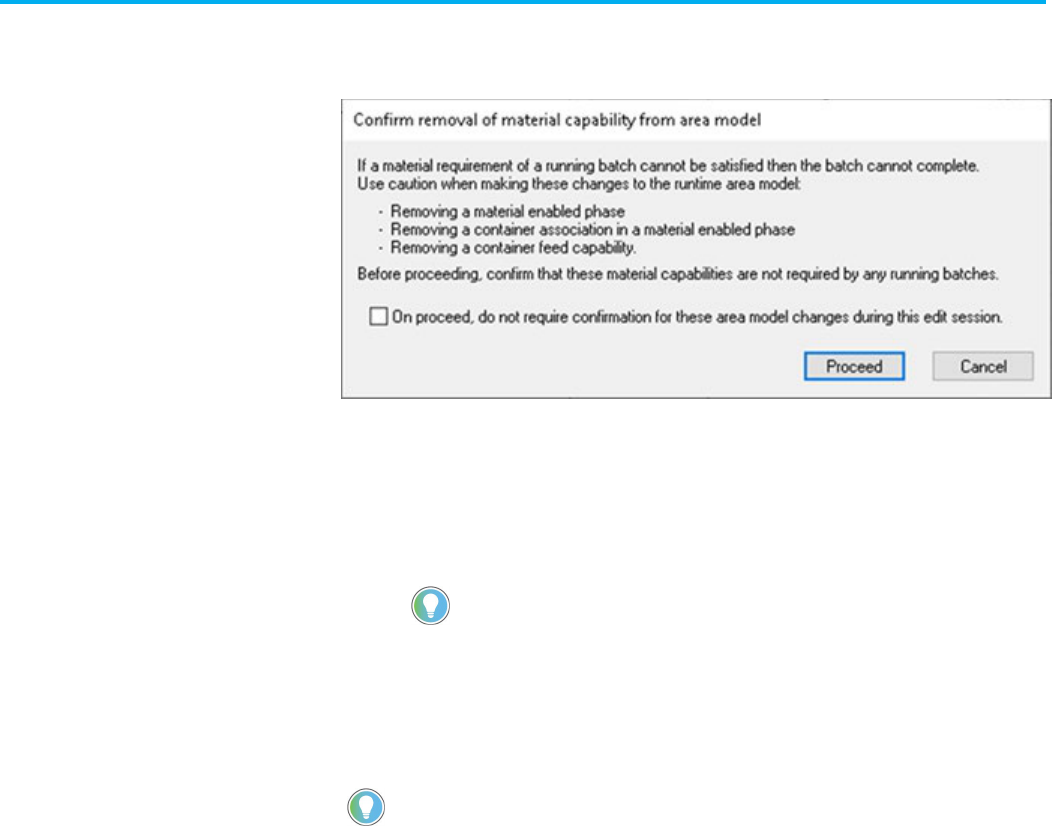
If a change to an area model removes a material capability that could
result in batches that are unable to complete due to the inability to satisfy
a material requirement, this confirmation message is displayed.
This confirmation will occur if any of these changes are made to the area
model:
• Removal or unsharing of a material enabled phase
• Removal of a container association from a material-enabled phase
• Removal of the distribution capability of a container association
• Removal of the addition capability of a container association
Tip: If you are making several edits to the material capabilities of the area model, select the
checkbox to not require confirmation of every subsequent edit.
To prepare an area model for deployment, an operator can verify that
changes made to the area model are permitted.
Then, the operator can deploy changes to the runtime area model.
Tip: An area model can also be verified and deployed from the FactoryTalk Batch Service Manager.
For more information about updating online area models, see the FactoryTalk Batch Administrator
Guide.
To verify an area model using the FactoryTalk Batch Equipment
Editor
1. Select Start > Rockwell Software > Equipment Editor.
2. Select File > Open.
3. Locate and select the area model file (.cfg) to be verified, and then
select Open.
4. Select File > Verify/Deploy....
5. In the Verify/Deploy Area Model dialog box, review the
information and select Verify Area Model to compare the original
area model with the changed area model.
6. If the verification is not successful, a message displays. Select
View Log to view the reason for the differences that are not
permitted.
7. Select Close.
Verify and deploy area
model

Chapter 2 Area models
Rockwell Automation Publication BATCH-UM004C-EN--D - November 2023 29
To deploy an area model using the FactoryTalk Batch Equipment
Editor
1. Select Start > Rockwell Software > Equipment Editor.
2. Select File > Open.
3. Locate and select the area model file (.cfg) to be deployed, and
then select Open.
4. Select File > Verify/Deploy....
5. In the Verify/Deploy Area Model dialog box, select Deploy Area
Model.
The Status area displays whether or not the deployment is
allowed. If it is not successful, a message displays. Select View
Log to view the details.
Tip: If an operator attempting to deploy an area model does not have FactoryTalk
permissions, the Deploy Area Model button is disabled.
6. Select Close.
IMPORTANT
The FactoryTalk eProcedure Server does not automatically pick up the changes
deployed to the area model. To update the eProcedure Server:
1. Open the
FactoryTalk Batch Service Manager
.
2. In
Service
, select
FactoryTalk eProcedure Server
.
3. In the
Server
area, clear the
Cold Boot
checkbox.
4. In
Service State
, click
Stop
, then click
Start/Continue
.
This performs a warm restart of the FactoryTalk eProcedure server that applies
the changes in the area model to the currently running batches.
The warm restart of the eProcedure Server while there are active instructions
will cause a phase communication error which may causes batches to be held.
See also
Area models on page 23

Rockwell Automation Publication BATCH-UM004C-EN--D - November 2023 31
Chapter 3
Import and export area models
FactoryTalk Batch gives the ability to import XML area models or export
area models to XML format. XML provides a standard, non-proprietary
format for distributing the area model configuration.
See also
Import an XML area model on page 31
Export an area model to XML on page 34
XML schemas and XML instance documents have become the industry
standard for providing implementation of neutral information. With
FactoryTalk Batch, FactoryTalk Batch Equipment Editor can import and
export an area model in XML format. This function allows for the
exchange of the area model information with other companies in a
standard, non-proprietary XML format. The area model information may
be edited using text editors or XML editors.
Tip: When securing an area model to a Security Authority Identifier, the Export command disables,
and the area model cannot export.
See also
Import an XML area model on page 31
Export an area model to XML on page 34
Convert XML to binary from the command line overview on page
34
When an XML area model imports, FactoryTalk Batch Equipment Editor
constructs the area model in memory. Save the imported area model to
the proprietary binary file or export it to another text file.
FactoryTalk Batch Equipment Editor validates the information provided
by the XML file. Only well-formed, validated XML files import. The XML
files must have the extension .axml to import. FactoryTalk Batch
Equipment Editor attempts to read the files as XML files only if the files
have the correct file extension.
Files with extensions other than .axml read as tab-delimited files.
Although the .txt file extension is expected for the tab-delimited text files,
FactoryTalk Batch Equipment Editor attempts to read all files with
extensions other than .axml as tab-delimited text files.
XML area models
Import an XML area model
Chapter 3 Import and export area models
32 Rockwell Automation Publication BATCH-UM004C-EN--D - November 2023
Tip: The YES_NO, MATERIALS, MATERIAL _CLASSES, and CONTAINERS enumeration sets recreate each
time a new area model creates, opens, or imports. Existing values are not imported. If the Material
Server is not available, the MATERIALS, MATERIAL_CLASSES, and CONTAINERS enumeration sets create
with the NULL_MATERIAL, NULL_CLASS, and NULL_CONTAINER default values only. (See
Import
enumerations for more information.)
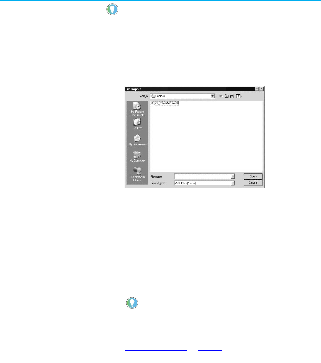
To import an XML area model:
1. Select Start > Rockwell Software > Equipment Editor.
2. Select File > Import.
3. From the Files of type list, select XML Files (*.axml).
4. Locate and select the XML file to import.
5. Select Open to initiate the import process. A message box
displays the name of each component imported and validated.
6. Select OK to complete the import process and return to
FactoryTalk Batch Equipment Editor.
7. Select File > Save As to save the newly imported file.
The Save As dialog box opens with Untitled.cfg highlighted in the
File name box.
8. In File name, type the new file name. Give the file the same name
as the currently selected area model to overwrite the current file.
9. Select Save. The new area model saves and the file name
displays on the FactoryTalk Batch Equipment Editor title bar.
Tip: If the file name is anything other than the area model currently selected in the Server
Options
dialog box, change the
Server Options
settings before the new area model is used.
See also
Import enumerations on page 32
Import system phase classes on page 33
Create and maintain these system enumeration sets in FactoryTalk
Batch Equipment Editor:
• PHASE_FAILURES
• YES_NO
• REPORTING_CONTEXTS
• MATERIALS (with an installed Material Server)
• MATERIAL_CLASSES (with an installed Material Server )
Import enumerations

Chapter 3 Import and export area models
Rockwell Automation Publication BATCH-UM004C-EN--D - November 2023 33
• CONTAINERS (with an installed Material Server)
With the exception of PHASE_FAILURES and
REPORTING_CONTEXTS, the data type or the members of these
system-maintained enumeration sets cannot change. The XML file must
include these system enumeration sets for validation against the
schema. These system enumeration sets cannot import.
Tip: The PHASE_FAILURES AND REPORTING_CONTEXTS system enumeration sets can import along
with any user-defined enumerations in these enumeration sets.
See also
Import an XML area model on page 31
Import system phase classes on page 33
FactoryTalk Batch Equipment Editor creates and maintains these
system phase class sets:
• $NULL
• $TIMER
On import of system phase classes, the entire phase class validates and
only those that match completely import.
Tip: If any of the system phase classes ($TIMER or $NULL) contain errors, only the first error show.
$NULL phase
The $NULL phase class validates:
• The name of the phase class must be $NULL.
• There must be no configured recipe or report parameters.
• There must be no configured messages.
• There must be no configured control strategies.
• There must be no configured request parameters.
• There must be no configured message partners.
• All other configurable values are not set.
$TIMER phase
The $TIMER phase class validates:
• The name of the phase class must be $TIMER_X (where X is the
type of Timer and the unit of measure; for example,
$TIMER_DN_SECOND or $TIMER_UP_DAY).
• There must be no configured messages.
• There must be no configured control strategies.
• There must be no configured request parameters.
• There must be no configured message partners.
Import system phase
classes

Chapter 3 Import and export area models
34 Rockwell Automation Publication BATCH-UM004C-EN--D - November 2023
See also
XML area models on page 31
FactoryTalk Batch allows export of an area model to a well-formed XML
format. With the exception of PHASE_FAILURES and
REPORTING_CONTEXTS, the data type or the members of the
system-maintained enumeration sets cannot change. The XML file must
include these system enumeration sets for validation against the
schema. These system enumeration sets can export but cannot import.
All system phases ($NULL or $TIMER) export. All associated recipe and
report parameters and associated data (for $TIMER_X phases) are part
of the export (for example, where X is the type of Timer and the unit of
measure; $TIMER_DN_SECOND or $TIMER_UP_DAY).
Tips:
• The PHASE_FAILURES AND REPORTING_CONTEXTS system enumeration sets export along with any
user-defined enumerations in these enumeration sets.
• When an area model secures to a FactoryTalk Network Directory Security Authority Identifier, the
Export command is disabled.
To export an area model to XML:
1. Select Start > Rockwell Software > Equipment Editor.
2. Select File > Open to open the area model.
3. Select File > Export. The File Export As dialog box opens.
4. Locate and select the file to export the area model or, in File
name, type a new file name.
5. In Save as type, select XML Files (*.axml).
6. Select Save to initiate the export process. If the file already exists,
confirm to replace the file.
7. Select OK to complete the export process and return to
FactoryTalk Batch Equipment Editor.
See also
Import and export area models overview on page 31
Convert XML area models to the proprietary binary format from the
command line using the supplied program AreaModelConvert.exe.
Only well-formed, schema-conformed, and program-validated XML files
convert.
When exporting from a command line, change to the directory containing
AreaModelConvert.exe and the paths cannot contain any spaces. UNC
names are also supported, as demonstrated in this syntax example:
The syntax for the command line is:
C:AreaModelConvert.EXE InputFile OutputFile LogFile
Where:
• InputFile specifies the path for the input XML filename.
• OutputFile specifies the path for output binary filename.
• LogFile specifies the path for log file.
Export an area model to
XML
Convert XML to binary from
command line

Chapter 3 Import and export area models
Rockwell Automation Publication BATCH-UM004C-EN--D - November 2023 35
Example:
C:AreaModelConvert.EXE
\\Batchctl\SampleDemo1\recipes\ice_cream1.axml
\\Batchctl\SampleDemo1\recipes\ice_cream1.cfg
\\Batchctl\SampleDemo1\logs\convert.log
The command line validates the information in the XML file and
overwrites the existing file specified by OutputFile. Error messages
append to the log file.
IMPORTANT
The command line program will not validate material-specific information, which
includes:
• Running status of the Material Server
• Existence of the referenced materials
• Existence of the referenced material classes
• Existence of the referenced containers
If the command line arguments are valid, the program returns a 0 (zero),
indicating a successful import. If the command line arguments are invalid,
the command line program returns a 1 (one), indicating a failure. View the
return code in the log file to check if the conversion succeeded or failed.
See also
Export an area model to XML on page 34

Rockwell Automation Publication BATCH-UM004C-EN--D - November 2023 37
Chapter 4
Enumerations overview
Enumerations are system objects that are defined as a variable data type
consisting of a numeric value (called an ordinal value) and an associated
text string. The process-connected device (PCD) and the FactoryTalk
Batch Server communicate using the numeric ordinal value. The server
then displays the ordinal value associated text string to the operator. Use
enumerations to display meaningful text to an operator, instead of a
number.
Enumeration sets contain groupings of related enumerations. The
FactoryTalk Batch and the PCD create and maintain these default
system enumeration sets:
• PHASE_FAILURES
• YES_NO
• MATERIALS (for Material Server-installed system)
• MATERIAL_CLASSES (for Material Server-installed system)
• CONTAINERS (for Material Server-installed system)
• REPORTING_CONTEXTS
The data type and the members of the YES_NO, MATERIALS,
MATERIAL_CLASSES, or CONTAINERS system-maintained
enumeration sets cannot change.
Create custom enumerations and enumeration sets within an area
model.
Use negative ordinal as shown in this example.
The agitator in Premixer B (Unit #2) might use:
Enumeration Set Name --> MOTORS
Enumeration Name
Ordinal
String
Enumeration_1 0 OFF
Enumeration_2
1
FORWARD
Enumeration_3
-1*
REVERSE
See also
System enumeration sets on page 37
Create enumeration sets on page 38
There are five default system enumeration sets. The data type or the
members of these system-maintained enumeration sets are not allowed
to change, except for the Phase_Failures and Reporting_Contexts
enumeration sets.
System Enumeration Set
Purpose
System enumeration sets

Chapter 4 Enumerations overview
38 Rockwell Automation Publication BATCH-UM004C-EN--D - November 2023
System Enumeration Set
Purpose
PHASE_FAILURES
By default, there are no members in this enumeration set.
Add enumerations based on the particular implementation
requirements.
IMPORTANT PHASE_FAILURES enumerations cannot have ordinal values greater than 32767 or less than 0 (zero).
REPORTING_CONTEXTS This enumeration set makes it possible to add reporting
context strings to phase class parameters and reports. The
events about the sets may be more easily queried and
sorted. Add, remove, and edit enumeration set members to
this enumeration set. The default enumeration is NULL,
with an ordinal value of 0.
PHASE_FAILURES and REPORTING_CONTEXTS are the only system enumeration sets to which enumerations can
be added. System enumeration sets display in bold text to differentiate them from custom enumeration sets.
YES_NO This is a simple enumeration set that contains two
members: NO with an ordinal value of 0 and YES with an
ordinal value of 1. This enumeration set cannot be
modified.
MATERIALS (for Material Server-installed system)
Represents the set of materials configured in the
FactoryTalk Batch Material Manager material database. The
default enumeration is NULL_MATERIAL, with an ordinal
value of 0. This value allows assignment of an enumeration
to a parameter of type MATERIALS, which delays the actual
material assignment until the recipe is built. All other
enumeration set members are recreated each time an area
model creates, opens, or imports, based on the material
data in the material database. The controller ID range for
Materials is from 1 through 9999999999.
CONTAINERS (for Material Server-installed system)
Represents the set of containers configured in the
FactoryTalk Batch Material Manager material database. The
default enumeration is NULL_CONTAINER, with an ordinal
value of 0. All other enumeration set members are
recreated each time an area model creates, opens, or
imports, based on the container data in the material
database. The controller ID range for Containers is from
1
through 9999999999.
If the FactoryTalk Batch Material Manager material database is unavailable, the MATERIALS and CONTAINERS
enumeration sets only contain the default enumerations.
The controller ID of a material and container is the ordinal value for the enumeration. If modified the controller ID
in the material database, the ordinal value of the associated enumeration changes, which could affect the phase
logic.
See also
Enumerations overview on page 37
Use these instructions to create enumeration sets.
To create enumeration sets:
1. Select Start > Rockwell Software > Equipment Editor.
Create enumeration sets

Chapter 4 Enumerations overview
Rockwell Automation Publication BATCH-UM004C-EN--D - November 2023 39
2. Select Edit > Enumeration Sets to open the Create
Enumeration Sets and Enumerations dialog box.
3. Under Sets, select New.
4. In the Create Enumeration Set dialog box, type the new
enumeration set name. Select OK to return to the Create
Enumeration Sets and Enumerations dialog box.
The new enumeration set name displays in the Enumeration Sets
column.
Tip: If members are not added to a new enumeration set, the set will not display as an option
in the
Enum/E.U
. list when updating phase class parameters and reports.
See also
Add enumeration members on page 39
Use these instructions to add enumeration members.
To add enumeration members:
1. Select Start > Rockwell Software > Equipment Editor.
2. Select Edit > Enumeration Sets to open the Create
Enumeration Sets and Enumerations dialog box.
3. Select the enumeration set.
4. Under Enumerations, select New.
Tip: Members to the system enumeration sets cannot be added: YES_NO, MATERIALS,
MATERIAL_CLASSES, and CONTAINERS.
5. Type the enumeration name and the ordinal value, or accept the
default ordinal value.
IMPORTANT
PHASE_FAILURES enumerations only support positive ordinals from 0 through
32767.
6. Select OK to return to the Create Enumeration Sets and
Enumerations dialog box. The new enumeration name displays
under Enumerations.
See also
Create enumeration sets on page 38
Edit enumerations and enumeration sets on page 40
Add enumeration members

Chapter 4 Enumerations overview
40 Rockwell Automation Publication BATCH-UM004C-EN--D - November 2023
Use these instructions to edit enumerations and enumeration sets.
Tip: The YES_NO, MATERIALS, MATERIAL_CLASSES, or CONTAINERS system enumeration sets cannot be
renamed or edited. PHASE_FAILURES and REPORTING_CONTEXTS are the only system enumeration
sets to which enumerations can be added. System enumeration sets display in
bold
text to
differentiate them from custom enumeration sets.
To edit enumerations and enumeration sets:
1. Select Start > Rockwell Software > Equipment Editor.
2. Select Edit > Enumeration Sets to open the Create
Enumeration Sets and Enumerations dialog box.
3. Select the enumeration set or enumeration to edit.
4. Select the corresponding Edit button (Sets or Enumerations).
5. If editing an enumeration, type the new enumeration name.
IMPORTANT
PHASE_FAILURES enumerations support positive ordinals from 0 to 32767 only.
6. If an unassigned enumeration set is being edited, the Edit
Enumeration Set Name dialog box displays. Type the new
enumeration set name and select OK to return to the Create
Enumeration Sets and Enumerations dialog box.
If editing an assigned enumeration set, a warning appears with a
list of the items with the enumeration assigned.
7. Select Yes to edit the enumeration set name. The items listed in
this dialog box modify to include the new enumeration set name.
Or, select No to cancel the modification.
8. Select OK to return to the Create Enumeration Sets and
Enumerations dialog box.
See also
Delete enumerations and enumeration sets on page 40
Use these instructions to delete enumerations and enumeration sets.
Tip: The system enumeration sets or members (enumerations) of the system enumeration sets
cannot be deleted: YES_NO, MATERIALS, MATERIAL_CLASSES, and CONTAINERS.
Edit enumerations and sets
Delete enumerations and
sets

Chapter 4 Enumerations overview
Rockwell Automation Publication BATCH-UM004C-EN--D - November 2023 41
To delete enumerations and enumeration sets:
1. Select Start > Rockwell Software > Equipment Editor.
2. Select Edit > Enumeration Sets to open the Create
Enumeration Sets and Enumerations dialog box.
3. Select the enumeration set or enumeration to delete.
4. Select Delete.
• If deleting an enumeration, continue to step 5.
• If deleting an enumeration set, skip to step 6.
5. To delete an enumeration:
• If the enumeration is not the default for a phase class
parameter, a warning displays verifying deletion of the
enumeration. Select Yes to delete the enumeration. Select No
to cancel the deletion.
• If the enumeration is the default for a phase class parameter
and Yes is selected to delete the enumeration, a message
displays stating that the enumeration cannot be deleted and
gives the phase class parameter name with this enumeration as
the default value. First, modify the phase class parameter to
remove the enumeration as the default value. Select OK to
close the warning dialog box and return to the Create
Enumeration Sets and Enumerations dialog box.
6. To delete an enumeration set:
Tip: Items that were using the deleted enumeration set are defaulted to Type = Integer and
Eng.Units = Eng.Units.
• A warning displays, verifying deletion of the enumeration set.
Select Yes to delete the enumeration. Select No to cancel the
deletion.
• A warning displays with a list of assigned items.
a. Select Yes to delete the enumeration set. A message displays the
number of tags, parameters, and reports that change from
deletion. Select OK to close the message dialog box and return to
the Create Enumeration Sets and Enumerations dialog box.
b. Select No to cancel the deletion.
c. Select Close to return to the Design View area.
See also
Edit enumerations and enumeration sets on page 40

Rockwell Automation Publication BATCH-UM004C-EN--D - November 2023 43
Chapter 5
Parameters and reports with FactoryTalk Batch
The FactoryTalk Batch Server uses parameters to send values to the
process-connected device (PCD). Reports return values from the PCD to
the FactoryTalk Batch Server. Use FactoryTalk Batch Equipment Editor
to configure parameters and reports for the phase. The phase instance
inherits the parameters and reports of the phase class from which it was
created.
See also
Parameters and reports in recipes on page 43
How parameters and reports work with phase tags on page 44
Batch parameters and reports on page 46
Material parameters on page 47
Scale parameters on page 48
When adding a phase class to an operation-level recipe using
FactoryTalk Batch Recipe Editor, the phase class parameters are
formula values, and the phase class reports are report values. When
defining the formula values, the recipe author has these options:
• Accept the default formula value (this is the corresponding phas
e
c
lass parameters default value).
• Assign a new value.
• Defer the formula value assignment to the operator or to a reci
pe
formula parameter - a parameter associated solely with the recipe.
U
sing parameters can minimize the number of phase classes or recipes
needed.
See also
Parameters warm restart support on page 202
Parameters example on page 43
If a plant has a unit that mixes several different products, define a phase
class to indicate the agitator’s speed in the mixer unit. Either define a
different phase class for each of the required speeds, or define one
phase class and configure a parameter for the agitator speed. When
using the phase class in a recipe, assign a value immediately or later. By
deferring the value assignment, one operation is created to use in
multiple recipes.
Parameters and reports in
recipes
Parameters example

Chapter 5 Parameters and reports with FactoryTalk Batch
44 Rockwell Automation Publication BATCH-UM004C-EN--D - November 2023
See also
Parameters and reports in recipes on page 43
A phase, which is an instance of a phase class in an area model, uses
tags to communicate with the engineered logic in the process-connected
device (PCD). Each tag in the phase maps to a specific memory address
or tag in the PCD where data associated with the phase is stored during
the recipe’s execution. The FactoryTalk Batch Server and the PCD use
the tags to exchange information regarding the phase.
Tip: The configuration for FactoryTalk Linx FactoryTalk Live Data tags is identical to that of OPC tags
Every OPC phase has a minimum of ten standard tags. When configuring
the phase class from which the OPC phase is created, define the number
of tags required for parameter and report communications, as well as
additional request tags.
Tip: For PhaseManager phases assigned to a Logix5000 CIP data server, it is not necessary to define
the number of parameter, report, and request tags. The correct number of tags automatically
configure when the area model synchronizes with the Logix Designer project.
See also
Additional request, parameter, and report tags for phases on page
44
Phase tags on page 45
A Request tag is one of the ten standard tags associated with every OPC
phase. The process-connected device (PCD) uses the Request tag to
request service from the FactoryTalk Batch Server. Sometimes, the PCD
neevds to communicate more information to the FactoryTalk Batch
Server than can be accommodated by the single standard Request tag.
For this purpose, specify on the phase class, the number of additional
request tags needed for an OPC phase.
Tip: For PhaseManager phases assigned to a Logix5000 CIP data server, do not configure request
tags. The tags automatically create for Logix5000 CIP phases when the area model synchronizes with
the Logix Designer project.
It is possible to configure a different number of phase class parameters
and reports than parameter and report tags for an OPC phase. Some
OPC phase logic programs may not want the number of parameters to
match the number of parameter tags, or the number of reports to match
the number of report tags.
To have the number of parameters and reports on the phase class
always equal the number of parameter tags and report tags on the
associated phases, enable Parameter/Tag Locking on the phase class.
If Parameter/Tag Locking is disabled, specify on the phase class the
number of parameter and report tags that exist on the associated OPC
phases. This number may be different from the number of defined phase
class parameters and reports for OPC phases.
Tip: For Logix5000 CIP phases, Parameter/Tag Locking always enables, regardless of the setting
selected. When the area model synchronizes with the Logix Designer project file, FactoryTalk Batch
Equipment Editor creates the same number of parameter tags as parameters that exist on the phase
class, and the same number of report tags as reports that exist on the phase class.
Parameters, reports, and
phase tags
Overview of tags for phases

Chapter 5 Parameters and reports with FactoryTalk Batch
Rockwell Automation Publication BATCH-UM004C-EN--D - November 2023 45
In summary, when creating the phase, specify the following:
• The number of parameters and reports associated with the phase
class.
• The number of tags in the phase associated with those
parameters, reports, and additional requests. Either enable
Parameter/Tag Locking, or specify the actual number of tags.
Tip: The configuration for FactoryTalk Linx FactoryTalk Live Data tags is identical to OPC tags.
When creating the OPC phase instance (phase assigned an OPC data
server), specify:
• The memory addresses or tags in the PCD associated with each
of the ten standard tags.
• The memory addresses or tags in the PCD associated with any
configured parameters, reports, and additional request tags.
Tip: If the number of phase tags does not equal the number of parameters for the specified
phase class (the number of phase tags should be equal to the highest parameter ID number),
the Upload/Download functionality does not operate correctly. Additionally, to correctly pass
parameter values, the phase logic must use request data parameters for specifying how
FactoryTalk Batch uploads the parameters.
See also
Phase class overview on page 137
Phase tags on page 45
Review the configuration of the process-connected device (PCD) to
verify that the number of tags configured for the OPC phase corresponds
to an equal number of tags in the PCD. The parameter and report data
types defined in FactoryTalk Batch Equipment Editor must be compatible
with the corresponding tag data types in the PCD.
Tip: The configuration for FactoryTalk Linx FactoryTalk Live Data tags is identical to that of OPC tags.
This table shows each parameter and report data type that can be
defined in FactoryTalk Batch Equipment Editor and its corresponding
data types that can be stored in PCD memory:
FactoryTalk Batch Equipment Editor
Data Type
Compatible PCD Data Types
Real
Real
Integer
Real, Integer
Enumeration
Real, Integer
String
String
See also
Additional request, parameter, and report tags for phases on page
44
Phase tags

Chapter 5 Parameters and reports with FactoryTalk Batch
46 Rockwell Automation Publication BATCH-UM004C-EN--D - November 2023
Parameters pass values from the FactoryTalk Batch Server to the
process-connected device (PCD). The PCD uses reports for returning
values to the server.
IMPORTANT
Do not use these words or phrases as parameter names or report names:
• all
• length
• recipepath
• outerhtml
• finalinstructions
• stepindex
• submitstring
• submit
Using these phrases as parameter or report names can cause errors during manual
phase control.
See also
Phase class parameters on page 46
Phase class reports on page 46
Phase class parameters pass from the FactoryTalk Batch Server to the
phase logic during the recipe phase’s execution. Phase class
parameters usually correspond to phase tags, which are addressed to
actual, configured parameters in the process- connected device (PCD).
When configuring the phase class, define phase class parameters. When
configuring the OPC phase, define the corresponding parameter tags,
including the address or tag in the PCD to which it is addressed.
Tip: For PhaseManager phases assigned to a Logix5000 CIP data server, the parameter tags
automatically create when the area model synchronizes with the Logix Designer project. Parameter
tags for Logix5000 CIP phases do not have to be defined.
See also
Phase class reports on page 46
Phase class reports values pass from the process-connected device
(PCD) to the FactoryTalk Batch Server. Report values contain data that
indicates how the phase functioned. They are in the event journal file
(.evt) for the running batch and can be in FactoryTalk Batch reports.
Phase class reports usually correspond to phase tags addressed to
configured parameters in the PCD.
Tip: The configuration for FactoryTalk Linx FactoryTalk Live Data report tags is identical to that of
OPC tags.
When configuring the phase class, define phase class reports for the
phase. When configuring the OPC phase, define the corresponding
report tags, including the address or tag in the PCD to which it is
addressed.
Tip: For PhaseManager phases assigned to a Logix5000 CIP data server, the report tags automatically
create when the area model synchronizes with the Logix Designer project. There is no need to define
report tags for Logix5000 CIP phases.
Batch parameters and
reports
Phase class parameters
Phase class reports

Chapter 5 Parameters and reports with FactoryTalk Batch
Rockwell Automation Publication BATCH-UM004C-EN--D - November 2023 47
See also
Phase class parameters on page 46
If using FactoryTalk Batch Material Manager with FactoryTalk Batch,
create material-enabled phase classes. Material-enabled phase classes
use system parameters that specify the material and amount of material
to use within a recipe.
The default parameters associated with a material-enabled phase class
are MATERIAL and AMOUNT. The default report parameters associated
with each material-enabled phase class are ACTUAL_AMOUNT and
FEED_COMPLETE. Each material-enabled phase class can be
assigned optional material parameters: CONTAINER, LOT, LABEL, and
MATERIAL_CLASS. The values of the MATERIAL, LOT, and LABEL
parameters are combined to create the material specification.
The material specification determines the container from which a material
is drawn or into which a material distributes when a batch runs. The
material specification always contains a material name. The specification
may include a lot name, a label, or both based on the container type.
See also
Types of containers on page 47
Default material parameters on page 47
FactoryTalk Batch Material Manager uses three types of containers:
Composite, Plug-Flow and Pallet. All three containers require the
material specification to contain at least a material name. Composite and
plug-flow containers support a material specification that includes a lot
name. Pallet containers support a material specification that includes a
lot name, or a label, or both.
If a material specification is only a material name, then any three of the
container types are valid. However, if a material specification includes a
material name, lot, and label, then only the pallet container type is valid.
See also
Default material parameters on page 47
Default material parameters:
Parameter
Purpose
MATERIAL Generally configured with the default value of NULL_MATERIAL; the actual material
is assigned in the recipe. Assign a material to the parameter, but then the phase
class can only be used to feed that specific material. The combination of the
MATERIAL parameter, the unit for the phase in which the phase class is running,
and the high and low values for the AMOUNT parameter determines if the phase
class is going to be an addition of material, distribution, or both.
FEED_COMPLETE
Reports that a material addition or distribution is complete. The ACTUAL_AMOUNT
report parameter records the actual quantity of material produced or consumed.
Material parameters
Types of containers
Default material
parameters

Chapter 5 Parameters and reports with FactoryTalk Batch
48 Rockwell Automation Publication BATCH-UM004C-EN--D - November 2023
Parameter
Purpose
MATERIAL
Generally configured with the default value of NULL_MATERIAL; the actual material
is assigned in the recipe. Assign a material to the parameter, but then the phase
class can only be used to feed that specific material. The combination of the
MATERIAL parameter, the unit for the phase in which the phase class is running,
and the high and low values for the AMOUNT parameter determines if the phase
class is going to be an addition of material, distribution, or both.
CONTAINER
Used to hold the name of the container to which a step is bound when a batch
runs. It is created with a default value of NULL_CONTAINER. The CONTAINER
parameter cannot be assigned a value in the area model or in a recipe.
Containers are considered to be equipment outside of the area model. Either the
FactoryTalk Batch Server or the operator determines the appropriate container to
which the step is bound. At that time, the value of the bound container name is
assigned to the CONTAINER parameter. Other than the default value, the
parameter only contains a value while the step is bound during run time.
MATERIAL_CLASS Represents a set of material classes configured in the material database. It is
created with a default value of NULL_CLASS. The only attributes of
MATERIAL_CLASS that can be modified are Default and Download on Start,
depending on whether or not control strategies are enabled.
LOT
Used to refine the list of materials to which a phase class can be bound. The lot
specifies a discrete quantity of a given material. When this parameter is blank at
run time, the FactoryTalk Batch Server binds to a container without regard to the
lot.
LABEL
Represents a sublot of a material, which is a discrete quantity of a given
material’s lot distributed to a specific container. In material addition phase
classes, the label is used to refine the material list to which a phase class can be
bound. In material distribution phase classes, the label is applied to the sublot of
material distributed into inventory.
Tip: The values of the optional material parameters (except for the MATERIAL_CLASS parameter)
within FactoryTalk Batch Equipment Editor cannot be edited.
See also
Types of containers on page 47
Select the Scale check box to set a parameter to automatically adjust
proportionally when a batch containing a phase based on this phase
class scaled at runtime.
For example, if a batch containing a phase based on this phase class
runs at a scale of 200%, the ADD_AMOUNT value automatically
increments by 200%. The ADD_AMOUNT adjusts to 100, since the
default is 50. Likewise, if the batch runs at a scale of 50%, the
ADD_AMOUNT adjusts to 25.
See also
Parameters and reports with FactoryTalk Batch on page 43
Scale parameters

Chapter 5 Parameters and reports with FactoryTalk Batch
Rockwell Automation Publication BATCH-UM004C-EN--D - November 2023 49
A parameter deviation occurs when the parameter or report value is
outside the acceptable range defined by the designer of the area model.
A verification policy defines the set of acceptable limits for each
parameter and the corresponding action to take when the parameter or
report value exceeds or falls short of the limits. The Verification Method is
the policy portion that defines the set of acceptable limits for a parameter
or report. When adding a parameter or report to a phase class, either
accept the default Verification Method, which is No Limits, or select a
different Verification Method.
Tip: To require electronic signatures as part of a Verification Policy, set up Signature
Templates before configuring the Verification Policy.
See also
Verification policies on page 151
Signature template on page 61
Create parameters and reports applicable to a specific phase class in
FactoryTalk Batch Equipment Editor. The parameters and reports are
directly associated with the phase class. All the parameters and reports
assume to be applicable to each recipe that includes the phase class.
However, some phase classes may assume different roles within a single
recipe or different roles across different recipes. In this situation, only a
subset of the parameters and reports associated with the phase class
may be required, resulting in unnecessary phase I/O when the recipe
executes. This is where control strategies are helpful.
Control strategies are user-defined groupings of phase class parameters
and reports that can be associated with a single phase class. Organizing
parameters and reports into separate control strategies allows phase
classes to assume multiple roles without generating unnecessary phase
I/O.
Create multiple control strategies for a phase class, each with its own
parameters and reports. Within a phase class associate parameters and
reports with a single or multiple control strategies. If a parameter or report
is associated with more than one control strategy, the value range,
engineering units, and the engineering units of the report can be defined
independently for each control strategy with which the parameter or
report is associated.
Tip: In FactoryTalk Batch Recipe Editor, when viewing recipe phase class enabled control strategies,
only the parameter values with specified control strategy display. Associating parameters with
specific control strategies eliminates the need for the recipe author or operator to determine which
phase class parameters, and report parameters are applicable when creating, viewing, and executing
a specific recipe.
See also
Control strategies example on page 49
Implement control strategies on page 50
This table represents the configured parameters, reports, and control
strategies for a single phase class. The table illustrates the relationship
Verification method for
parameter deviations
Control strategies overview
Control strategies example

Chapter 5 Parameters and reports with FactoryTalk Batch
50 Rockwell Automation Publication BATCH-UM004C-EN--D - November 2023
between parameters, reports, and control strategies. An X placed below
a control strategy indicates that the parameter or report is associated with
that control strategy.
Parameter Name
CONTROL_STRA
TEGY_1
CONTROL_STRA
TEGY_2
Strategy 1
Value
Strategy 2
Value
PARAMETER_A
X
150
PARAMETER_B
X
X
200
275
PARAMETER_C
X
70
REPORT_A
X
X
125
125
For example, a phase class contains three phase class parameters,
PARAMETER_A, PARAMETER_B, and PARAMETER_C, and a report
parameter named REPORT_A. As indicated above, a parameter can
associate with only one control strategy as is the case with
PARAMETER_A and PARAMETER_C. Or, a parameter associate with
more than one control strategy as is the case with PARAMETER_B and
REPORT_A. Parameters associated with more than one control strategy
can have separately defined values for each control strategy as indicated
by PARAMETER_B.
See also
Implement control strategies on page 50
Configure the phase class in an area model to enable or disable the
control strategy functionality. For phase classes that have the control
strategy functionality enabled, configure one or more strategies for that
phase class. Assign phase class parameters and reports to each control
strategy, as well as configure their ranges, values, and engineering units.
When creating master recipes using FactoryTalk Batch Recipe Editor,
specify which control strategy to use for each instance of the phase class
within the recipe.
When the recipe executes, the phase class uses only the parameters
associated with the control strategy specified during recipe creation.
Likewise, when the executed recipe is viewed in the FactoryTalk Batch
View or other client program, a control strategy-enabled phase class only
displays the specified control strategy and any parameters associated
with that control strategy.
However, the default values of parameters associated with control
strategies can be changed.
Additionally, if a phase class is executed using manual phase control,
select which control strategy to use before running the phase class.
Tip: Configure the tags in the phase and the phase logic in the process-connected device(s) (PCD) to
support control strategy use.
When a PCD requests to download phase class parameters or upload phase class reports, only the
appropriate phase class parameters and reports are loaded, based on the control strategy.
Configure and map the phase class and report parameters to the tags in the PCD(s).
Implement control
strategies

Chapter 5 Parameters and reports with FactoryTalk Batch
Rockwell Automation Publication BATCH-UM004C-EN--D - November 2023 51
See also
Configure phase class control strategies on page 149
Use the download parameter subsets to define subsets of phase class
parameters for Download (DL) on Start and Download (DL) on
Transfer of Control (TOC). These subsets provide for a more efficient
batch execution. Also, the upload report subsets allows definition of a
subset of the phase class reports for Upload (UL) on Terminal State or
Upload (UL) on Transfer of Control (TOC). These subsets provide for
a more efficient process.
Tip: Transfer of control means that two instances of the same phase exist in a recipe and are
separated by a recipe transition condition containing something other than <Phase Name>.State =
Complete. In this case, the running logic does not terminate when the transition condition becomes
true.
Assign parameters to none, one, or both of the upload/download sets. By
assigning a parameter or report to a subset, that parameter or report,
along with the other members of the subset, are downloaded
(parameters) or uploaded (reports) when the appropriate phase logic
request is issued.
Tip: The 145 (Request Failed) command value can be issued by the FactoryTalk Batch Server when
processing a phase logic request experiences an error. This enhanced error handling phase logic
protocol is supported by making a request where the value is 10,000 greater than the current
standard requests.
For example, to upload a report parameter using the enhanced phase logic request, add 10,000 to the
standard request code of 2200 to get the enhanced request code of 12200.
IMPORTANT
When using Auto Upload with the FactoryTalk Batch Server configured for Warm or
Warm All Restart, the Server may upload addition material information twice when a
phase is transitioned to External during the upload. Check the journal file. If the upload
has occurred twice, manually adjust the amount in the material database. The setpoint
of the amount parameter is recalculated with each warm restart as well. This number
may need to be manually updated.
See also
Phase class with different subsets example on page 51
Download parameter requests on page 52
Upload report requests on page 53
Configure phase class parameters on page 140
Configure phase class reports on page 144
This table is an example of a phase class and how its parameters and
reports can be assigned to the different subsets:
AGITATE_1
Parameters
DL on
Start
DL on
TOC
Reports
UL on
Terminal
State
UL on TOC
SPEED X X AGITATE_TIME X X
TIME
X
X
AVG_TEMP
X
LEVEL
X
AVG_SPEED
X
X
Parameter and report
subsets
Phase class with different
subsets

Chapter 5 Parameters and reports with FactoryTalk Batch
52 Rockwell Automation Publication BATCH-UM004C-EN--D - November 2023
TEMP
X
AMT_DUMPED
X
See also
Parameter and report subsets overview on page 51
Download parameter requests on page 52
Upload report requests on page 53
Download parameter subsets allows definition of subsets of parameters
downloaded to the process-connected device (PCD) when the
appropriate phase logic requests are sent to the FactoryTalk Batch
Server.
• If DL on Start is selected, the FactoryTalk Batch Server
downloads these parameters to the PCD before the FactoryTalk
Batch Server issues a START command to the phase. Once the
download is verified, the FactoryTalk Batch Server starts the
phase. The phase logic can explicitly request this or the phase can
be configured for the FactoryTalk Batch Server to automatically
download these parameters before it issues a START command.
• If DL on TOC is selected, the parameters may be downloaded to
the PCD when a transfer of control situation occurs. Transfer of
control means that two instances of the same phase exist in a
recipe and are separated by a recipe transition condition that
contains something other than <Phase Name>.State = Complete.
In this case, the phase’s running logic does not terminate when the
transition condition becomes true. When the transition condition
becomes true, the phase logic must explicitly request the Server to
download the transfer of control subset of parameters to the PCD.
To download only the parameters assigned to the DL on Start subset,
use these download requests:
(OPC or FTD) phases
Logix5000 CIP phases
1501 or 11501 request
PXRQ instruction,
External request: Download Input Parameters
Subset
DINT[0] - 1
To download only the parameters assigned to the DL on TOC subset,
use these download requests:
(OPC or FTD) phases
Logix5000 CIP phases
1502 or 11502 request
PXRQ instruction,
External request: Download Input Parameters
Subset
DINT[0] - 2
When one of these requests is issued, each parameter is downloaded to
the memory address or tag in the PCD that corresponds to the parameter
tag in the phase.
See also
Parameter and report subsets overview on page 51
Download parameter
requests

Chapter 5 Parameters and reports with FactoryTalk Batch
Rockwell Automation Publication BATCH-UM004C-EN--D - November 2023 53
Upload report requests on page 53
Configure phase class parameters on page 140
Configure phase class reports on page 144
If UL on Terminal State is selected, the FactoryTalk Batch Server
uploads this subset of reports from the process-connected device (PCD)
after the phase logic transitions to a terminal state of COMPLETE,
STOPPED, or ABORTED. The phase logic can explicitly request the
server to upload these reports or the phase can be configured for the
server to automatically upload these reports after the phase logic
transitions to a terminal state.
If UL on TOC is selected, the reports are uploaded to the PCD when a
transfer of control situation occurs. In this case, the phase logic must
explicitly request the FactoryTalk Batch Server to upload the transfer of
control report subset from the PCD.
To upload only the reports assigned to the UL on Terminal State
subsets:
(OPC or FTD) phases
Logix5000 CIP phases
2501 or 12501 request
PXRQ instruction,
External request: Upload Output Parameters Subset
DINT[0] - 1
To upload only the reports assigned to the UL on TOC subset:
(OPC or FTD) phases
Logix5000 CIP phases
2501 or 12501 request
PXRQ instruction,
External request: Upload Output Parameters Subset
DINT[0] - 2
See also
Parameter and report subsets overview on page 51
Automatic Upload/Download decreases batch duration time as well as
the amount of phase logic programming required. Automatic
Upload/Download works with Download Parameter Subsets and
Upload Report Subsets. Automatic Upload/Download allows the
FactoryTalk Batch Server to automatically download parameters
grouped into the download on START subset or to upload reports
grouped into the upload on terminal state subset. Phase logic can be
developed to make these requests; however, it is not required.
Use Automatic Upload/Download to configure the FactoryTalk Batch
Server to:
• Automatically download the parameters grouped into the
download on start subset when all the conditions required to start
the phase are true.
• Automatically upload the appropriate report values grouped into
the upload on terminal state subset when the phase transitions to
a terminal state of COMPLETE, STOPPED, or ABORTED.
Automatic Upload/Download eliminates the need to send the download
on start or upload on Terminal State request from the phase logic to the
FactoryTalk Batch Server.
Upload report requests
Automatic
Upload/Download

Chapter 5 Parameters and reports with FactoryTalk Batch
54 Rockwell Automation Publication BATCH-UM004C-EN--D - November 2023
Tip: Downloading parameters on Transfer of Control and uploading reports on transfer of control is
not automatic and still requires a phase logic request.
The Automatic Download Parameter Upon Start and UL On Terminal
State are configured for each individual phase (as long as the
parameters and reports of the phase class from which the phase was
created are grouped into the appropriate subsets). The Automatic
Download parameter Upon Start and UL on Terminal State may also
be configured independently of each other on a phase. For UL on
Terminal State, specify any or all terminal states for which the automatic
function is applicable: COMPLETE, STOPPED, or ABORTED.
Tip: The 145 (Request Failed) command value can be issued by the FactoryTalk Batch Server when
processing a phase logic request experiences an error. This enhanced error handling phase logic
protocol is supported by making a request where the value is 10,000 greater than the current
standard requests.
For example, to upload a report parameter using the enhanced phase logic request, add 10,000 to the
standard request code of 2200 to get the enhanced request code of 12200.
See also
Parameter and report subsets overview on page 51
Control strategies with upload/download parameter subsets on
page 54
Configure the general data for a phase on page 162
If parameters or reports are assigned to Upload/Download Parameter
Subsets, and Control Strategies are enabled, only those parameters
common to all the involved subsets and selected Control Strategy are
uploaded or downloaded.
In this example, the phase class has a number of reports and
parameters. The control strategies are enabled and the CS1 control
strategy is the default. When a phase logic request:
• Is issued for Download on Start, only the SPEED, TIME, LEVEL,
and TEMP parameters are included.
• Is issued for Download on TOC, only the SPEED and TIME
parameters are included.
• For Upload on Terminal State is issued, only the AVG_SPEED,
AGITATE_TIME, AVG_TEMP, and AMT_DUMPED reports are
included.
• For Upload on TOC is issued, only the AVG_SPEED and
AGITATE_TIME reports are included.
AGITATE_1 (Control Strategies enabled; CS1 is the default control strategy)
Parameters
DL on
Start
DL on
TOC
CS1
Reports
UL on
Terminal
State
UL on
TOC
CS1
SPEED X X X AVG_SPEED X X X
TIME
X
X
X
AGITATE_TIME
X
X
X
LEVEL
X
X
AVG_TEMP
X
X
TEMP
X
X
AMT_DUMPED
X
X
Control strategy with
parameter subset


Rockwell Automation Publication BATCH-UM004C-EN--D - November 2023 57
Chapter 6
Electronic signatures
An electronic signature is an electronic representation of a signature and
its associated data, including:
• Signoff meanings (such as review, approval, responsibility, or
authorship)
• Signer comments
• Signer security requirements
• Date and time of signatur
e
An electronic signature in the FactoryTalk Batch system can consist of
signoffs by one, two, or three FactoryTalk users or groups.
See also
Types of electronic signatures on page 57
How electronic signatures work on page 57
Signature template on page 61
Signatures can be configured for verification of these runtime
FactoryTalk Batch events:
• Report parameters for automated and manual (eProcedure)
phases.
• Changes to the recipe parameter values made by operators from
the FactoryTalk Batch View or FactoryTalk Batch View HMI
C
ontrols.
• Completion of eProcedure steps.
• Batch or phase commands issued by operators from FactoryTalk
Batch View or FactoryTalk Batch View HMI Controls.
• General usage that can be configured to display at any time w
hen
ex
ecuting an automated or manual phase.
Electronic signatures are stored in the FactoryTalk Batch Event Journal
with their corresponding electronic records. These electronic signatures
include all the components necessary for compliance with 21 CFR Part
11.
See also
Electronic signatures on page 57
The steps involved in configuring and executing electronic signatures
span the FactoryTalk Batch product suite.
• The FactoryTalk Batch system administrator sets up electronic
Types of electronic
signatures
How electronic signatures
work

Chapter 6 Electronic signatures
58 Rockwell Automation Publication BATCH-UM004C-EN--D - November 2023
signature and signoff security.
IMPORTANT
Changing the FactoryTalk Directory Server after configuring electronic
signatures using FactoryTalk Security is not supported. Doing so may cause
Signature Signoffs to fail.
• In FactoryTalk Batch Equipment Editor, the FactoryTalk Event
Archiver event filters for the signature events to capture for use in
FactoryTalk Event Archiver with Reporting Services reports, or
other reports.
• Create signature templates for the area model. To obtain
electronic signatures for recipe parameters and report parameters
of specific phase classes, configure the verification method and
signature template to be used when the phase class is created or
edited. To download all the limits information to the phase logic,
map parameter tags and report tags to the appropriate limit tags
on the phases. To require signature verification for the execution
of specific commands, set up command verification policies in
FactoryTalk Batch Equipment Editor using the signature templates
that were created.
When the master recipe builds, the recipe parameter limits that trigger
the verification policy default from the parameter limits specified on the
equipment phase. Change these values at the recipe level in FactoryTalk
Batch Recipe Editor. If configured a phase class to obtain a signature for
deviation of report limits, specify those limits on the report for the phase
class in FactoryTalk Batch Recipe Editor.
When a batch runs and parameter or report deviations occur requiring
signature verification, or the operator issues commands requiring
signature verification, a signature is added to the signature list in
FactoryTalk Batch View, the Electronic Signature HMI Controls, or the
eProcedure client, prompting the appropriate users to enter signatures.
All signatures record as Signature events in the FactoryTalk Batch Event
Journal viewer in FactoryTalk Batch View.
Once signature event data generates, create FactoryTalk Event Archiver
reports, or other reports that capture electronic signature data.

Chapter 6 Electronic signatures
Rockwell Automation Publication BATCH-UM004C-EN--D - November 2023 59
This flowchart shows the sequence of tasks in the setup and
configuration, execution, viewing, and reporting of electronic signatures:

Chapter 6 Electronic signatures
60 Rockwell Automation Publication BATCH-UM004C-EN--D - November 2023

Chapter 6 Electronic signatures
Rockwell Automation Publication BATCH-UM004C-EN--D - November 2023 61
See also
Electronic signatures on page 57
Signature template on page 61
Before setting up phase classes and recipes to require electronic
signatures, establish a set of signature templates. Each signature
template defines the number of signoffs required, the meaning of those
signoffs, whether comments are included with the signoff, and which
users or user groups have the required security permissions to complete
the signoff. Create as many templates as needed to distinguish the
different signature types the business processes requires.
The process of creating a signature template consists of three main
procedures:
• Add a signature template
• Configure signature template signoffs
• Assign security permissions for a signoff
See also
Edit signature templates dialog box on page 61
Add a signature template on page 62
Configure signature template signoffs on page 63
Delete a signature template on page 67
Modify a signature template on page 68
The Edit Signature Templates dialog box contains:
Name
Purpose
General tab
Template Name
Displays the name of the template selected in the Signature Templates list.
If there are no templates in the template list, this is disabled.
• Template names must be unique, and can range from 1 through 50
characters in length.
• The name must begin with an alpha character (a-z or A-Z) and may be
followed with any combination of alphanumeric characters or under
score.
•
Template Name
is not case sensitive.
• Spaces are not valid.
Template Index
The unique identification number of the template selected in the Signature
Templates list. This value must be a positive integer from 1 to 2,147,483,647.
Signoffs Required
The number of signatures required in the verification policy this template
represents.
Last Signoff A number indicating which signoff must be completed last, after other
signatures have been entered. If
None
is selected, the signatures may be
entered in any order.
New Template Opens the
Create Signature Template
dialog box where new templates can
be added to the Signature Templates list.
Delete Template
Removes the selected Signature Template form the list. If the selected
template is used by the verification policy of any commands, phase class
parameters, or reports, the template cannot be deleted.
Signoffs tab
Signature template
Edit signature templates
dialog box

Chapter 6 Electronic signatures
62 Rockwell Automation Publication BATCH-UM004C-EN--D - November 2023
Name
Purpose
Template Name
Lists the templates that have been added on the General tab. Select the
template to see its signoff information or to configure signoffs.
Signoff
Each number in the list represents a required signature for the selected
template. These values are determined by the value selected in the
General
tab
Signoffs Required
box. Select the number of the Signoffs. Consider
which value was selected in the General tab Last Signoff box.
Meaning
(optional) Type a short phrase describing the significance of the selected
signoff.
For example, Command Authorized by Signer, Done By Signer, or Checked by
Signer.
The
Meaning
displays as part of the signoff event recorded in the
FactoryTalk Batch event journal. The
Meaning
box can range from 0 through
80 characters, and can contain any viewable and printable character.
Special control or non-printable characters are not valid.
Comment Select whether a comment is
Optional
,
Required
, or
Not Allowed
by the
signer at the time the signoff is entered.
Security Permissions Displays the users and groups of users that can complete the selected
signoff. If this area is blank, no security permissions have been configured
yet. Security Permissions must be configured for all signoffs before the
Edit
Signature Templates dialog box can be closed.
Add Opens the
Select User or Group
dialog box. Select which users and groups
have permission to complete the selected signoff.
Delete
Removes the selected user or group from the Security Permissions box, and
removes the user or group permission to complete the selected signoff.
See also
Delete a signature template on page 67
Use these instructions to add a signature template.
To add a signature template:
1. Select Start > Rockwell Software > Equipment Editor.
2. Select File > Open, and then select the area model file.
3. Select Edit > Signature Templates to open the Edit Signature
Templates dialog box.
Add a signature template

Chapter 6 Electronic signatures
Rockwell Automation Publication BATCH-UM004C-EN--D - November 2023 63
4. Select New Template to open the Create Signature Template
dialog box.
5. In the Template Name box, enter a unique name to identify the
template. The name must begin with an alpha character (a through
z or A through Z) and may be followed with any combination of
alphanumeric characters or underscores. This box is not case
sensitive. Spaces are not accepted as valid input.
Tip: Choose a name that easily identifies the template properties or purpose. The template
name is used to identify the signature template when the command verification policies,
phase classes, and recipes are being configured.
6. (optional) A unique identification number is defaulted in the
Template Index box. If needed, change this number (must be a
positive integer).
IMPORTANT
If a decimal is entered in the Template Index box, the value is automatically
rounded up or down to the nearest integer. If the nearest integer is already
assigned to another template, a duplicate index value error message is opened.
7. Select OK. The Create Signature Template dialog box closes
and the new template is listed in the Signature Templates list in
the Edit Signature Templates dialog box.
8. In the Signoffs Required list, select the number of signatures that
must be obtained for this signature template.
9. In the Last Signoff list, select the number of the signoff that
corresponds to the signature that must be completed last (that is,
after other signatures have been entered). If the signatures do not
have to be completed in any particular order, select None.
10. Configure the signoffs for the signature template.
See also
Configure signature template signoffs on page 63
Use these instructions to configure the signature template signoffs.
Set signature template
signoffs

Chapter 6 Electronic signatures
64 Rockwell Automation Publication BATCH-UM004C-EN--D - November 2023
Prerequisite
• Verify the signature template has been added.
To configure signature template signoffs:
1. Select Start > Rockwell Software > Equipment Editor.
2. From the Edit Signature Templates dialog box, select the
Signoffs tab.
3. From Template Name, select the template to configure signoff
information.
4. From Signoff, select the number that represents the signoff to
configure.
Tip: This Signoff list corresponds to the Signoffs Required list on the General tab. When
completing these steps, keep in mind the number selected for
Last Signoff
on the
General
tab.
5. (optional) In Meaning, enter a short phrase that describes the
significance of this signoff.
Tip: The
Meaning
displays as part of the signoff event recorded in the FactoryTalk Batch
event journal.
6. From Comment, select whether signer comments are Optional,
Required, or Not Allowed.
7. Under Security Permissions, assign privileges to the users and
groups authorized to complete this signoff.

Chapter 6 Electronic signatures
Rockwell Automation Publication BATCH-UM004C-EN--D - November 2023 65
When finished assigning security permissions for the signoff, the
User and Group names are displayed in the Security
Permissions area. (For detailed instructions, see Assign
security permissions for a signoff.)
8. Select Apply.
9. If creating a template that requires more than one signoff, repeat
steps 3 through 7 until all the signoffs have been configured for the
template.
Tip: When a signature requires multiple signoffs, each signoff must be made using a unique
UserID and password.
10. When finished configuring all the signoffs for the template,
either return to the General tab to add other signature templates,
or select OK to close the dialog box.
See also
Add a signature template on page 62
Assign security permissions for a signoff on page 65
Remove signoff permissions for a user or group on page 67
When configuring signoffs for a signature template, specify which users
or groups may complete each signoff.
Prerequisite
• Add a signature template.
• On the Signoffs tab, enter a Template Name, select a Signoff
number and Comment option, and enter a Meaning.
To assign security permissions for a signoff:
1. Select Start > Rockwell Software > Equipment Editor.
2. From the Edit Signature Templates dialog box, select Signoffs
tab.
Set security permissions
for a signoff

Chapter 6 Electronic signatures
66 Rockwell Automation Publication BATCH-UM004C-EN--D - November 2023
3. From the Security Permissions area, select Add. The Select
User or Group dialog box opens.
4. In the Select User or Group dialog box, select Show all to view a
list of all users and groups. The list displays all FactoryTalk
Security users and groups and all Windows-linked users and
groups defined in the FactoryTalk Directory Server.
Tip: Changing the FactoryTalk Directory Server after adding users and groups to a signature
template is not supported and may cause signature signoffs to fail.
5. Select the appropriate user or group.
6. Select OK.
IMPORTANT
Changing the FactoryTalk Directory Server after configuring electronic
signatures using FactoryTalk Security is not supported and may cause
signature signoffs to fail.
See also
Add a signature template on page 62
Configure signature template signoffs on page 63

Chapter 6 Electronic signatures
Rockwell Automation Publication BATCH-UM004C-EN--D - November 2023 67
Complete these steps to remove authority from an individual or group to
complete a particular signoff.
To remove signoff permissions for a user or group:
1. Select Start > Rockwell Software > Equipment Editor.
2. Select Edit > Signature Templates, select the template, and then
select the Signoffs tab.
3. Under Security Permissions, select the individual or group.
4. Select Delete.
5. Select OK.
See also
Add a signature template on page 62
A signature template cannot be deleted if it is used in:
• The verification policy for any command.
• The verification policy for phase class parameters or reports.
• The approval process for a recipe.
Before you begin:
• Modify each command verification policy that uses the template to
use a different signature template or to not require signature
verification.
• Modify the verification policy for phase class parameters or reports
to use a different signature template or no signature template, or
Remove signoff
permissions
Delete a signature template

Chapter 6 Electronic signatures
68 Rockwell Automation Publication BATCH-UM004C-EN--D - November 2023
the parameter or report must be deleted before the template
currently in use can be deleted.
• Modify recipe approval step to have a different signature template
assigned to its signoff.
To delete a signature template:
1. Select Start > Rockwell Software > Equipment Editor.
2. Open the area model file.
3. Select Edit > Signature Templates.
4. On the Edit Signature Templates dialog box, from Signature
Templates, select the template to delete.
5. Select Delete Template. The template name is removed from the
Signature Templates list.
6. Select OK.
See also
Command verification policies on page 69
Modify a signature template on page 68
The Template Name or Template Index cannot be modified if the
signature template is currently used in the verification policy of any
command, phase class parameters, or reports, or if assigned to a recipe
approval step.
Before you begin:
• Modify each command verification policy that uses the template to
use a different signature template or to not require signature
verification.
• Modify the verification policy for phase class parameters or reports
to use a different signature template or no signature template, or
the parameter or report must be deleted before the template
currently in use can be deleted.
• Modify recipe approval step to have a different signature template
assigned to its signoff.
IMPORTANT
If the number of Signoffs Required for a template is changed, the value of Last
Signoff may also be affected. If the change results in the value of Last Signoff
being greater than the value of Signoffs Required, the value of Last Signoff
automatically changes to None. To enforce a different signature as the last
signoff, select a different value in Last Signoff.
For example, the value of Signoffs Required is 3 and Last Signoff is 3. If Signoffs
Required is changed to 2, the value of Last Signoff is automatically changed to
None.
To modify a signature template:
1. Select Start > Rockwell Software > Equipment Editor.
2. Open the area model file.
3. Select Edit > Signature Templates.
Modify a signature template

Chapter 6 Electronic signatures
Rockwell Automation Publication BATCH-UM004C-EN--D - November 2023 69
4. On the Edit Signature Templates dialog box, in Signature
T
emplates, select the template to modify.
5. On the General tab and modify boxes as needed.
6. Select OK.
See also
Command verification policies on page 69
Set up command verification policies to obtain signatures for batch or
phase commands issued by operators from FactoryTalk Batch View or
HMI Controls.
Before configuring command verification policies, create signature
templates that describe the signoff policies to use for the commands.
IMPORTANT
If signature verification for the Remove command is enabled, all AUTOREMOVE executes
sent to the FactoryTalk Batch Server fail and generate an error message. The
AUTOREMOVE execute tells the server to automatically remove a batch when its state
reaches COMPLETE.
See also
Signature template on page 61
Add a signature requirement to commands on page 69
Change the verification policy for a command on page 70
Remove the signature requirement for a command on page 70
Follow these instructions to add electronic signatures to commands.
1. Select Start > Rockwell Software > Equipment Editor.
2. Select Edit > Command Policies.
Tip: The ability to secure FactoryTalk eProcedure instruction files does not currently exist in
FactoryTalk Security, require an electronic signature on Parameter Change to prevent
unauthorized users from executing instructions.
3. Select the checkbox next to the command that requires an
el
ectronic signatur
e.
4. Fr
om Select Template, select the signature template that defines
the signature policy to use for this command.
5. Select OK. The Select Signature dialog box closes, and the
signature template displays in the Signature Template box next
to the s
elected command.
6. Repeat these steps for each additional command that requires an
electronic signature.
7. Select OK.
See also
Edit command verification policies dialog box on page 70
Change the verification policy for a command on page 70
Remove the signature requirement for a command on page 70
Command verification
policies
Add electronic signatures
to commands

Chapter 6 Electronic signatures
70 Rockwell Automation Publication BATCH-UM004C-EN--D - November 2023
The components in the Edit Command Verification Policies dialog box
include:
Name
Purpose
Command
This column displays each command that can be configured to require an
electronic signature (view only).
Requires Signature
Opens the Select Signature Template dialog box. Select the check box next to
each command that should require an electronic signature when it is executed.
Signature Template Displays the signature template that defines the verification policy for the
command. If the command does not require a signature, this box is disabled. To
change the
Signature Template
, select browse ( ) and select a different
template in the Select Signature Template dialog box.
See also
Add a signature requirement to commands on page 69
If a command requires a signature and has a signature template
specified, follow these instructions to change the verification policy for
the command.
Prerequisite
• Verify a signature template already exists that describes the new
signoff policies to use. If not, create one.
To change the verification policy for a command
1. Select Start > Rockwell Software > Equipment Editor.
2. Select Edit > Command Policies.
3. Select browse ( ) next to the signature template to change.
4. On the Select Signature Template dialog box, from Select
Template, select the signature template that defines the signature
policy used for this command.
5. Select OK. The Select Signature dialog box closes. The
signature template chosen displays in the Signature Template
box next to the selected command.
6. Repeat these steps for each additional verification policy to
change.
7. Select OK.
See also
Signature template on page 61
Command verification policies on page 69
To remove the verification policy and signature requirement for a
command, complete these steps.
Edit command verification
policies
Change a command
verification policy
Remove signature
requirement commands

Chapter 6 Electronic signatures
Rockwell Automation Publication BATCH-UM004C-EN--D - November 2023 71
To remove the signature requirement for a command
1. Select Start > Rockwell Software > Equipment Editor.
2. Select Edit > Command Policies.
3. Clear the Requires Signature check box next to the appropriate
command.
The Signature Template box is disabled and the template name
appears shaded. This indicates that the signature template is not
in use for this command and no signature verification is required.
Tip: To re-enable the signature requirement for a command, select the Requires Signature
check box. The signature template previously used automatically activates.
4. Select OK.
See also
Add a signature requirement to commands on page 69
Command verification policies on page 69

Rockwell Automation Publication BATCH-UM004C-EN--D - November 2023 73
Chapter 7
Recipe approval process overview
The recipe approval process validates the development and
maintenance of batch recipes. Using signature certification, the recipe
approval process safeguards design workflow in a formalized manner.
This ensures that each recipe is validated by authorized personnel before
being released to production, or released as a component within a larger
recipe.
The Recipe Approvals process is configured and enabled in the
FactoryTalk Batch Equipment Editor, then executed in the FactoryTalk
Batch Recipe Editor. When the approvals process is complete, the recipe
is added to the Recipe List in FactoryTalk Batch View. At that point,
production batches can be made from the recipe.
In addition to the primary approval process with up to six approval steps
(three optional), a two-step expedited approval process is available. Both
primary and expedited processes provide a revert option to allow forward
and reverse progress through the recipe approval process.
See also
Recipe approval tasks on page 73
Configure recipe approval steps on page 74
Edit a recipe approval on page 77
Disable recipe approval on page 77
As a necessary first step, a FactoryTalk Batch system administrator sets
up electronic signatures for signoff security.
Typically, an administrator, or a process engineer with full administrative
rights, then defines signature templates in FactoryTalk Batch Equipment
Editor. Signature templates define which users can sign off on recipe
approval steps, either to approve or to revert the step.
Also in FactoryTalk Batch Equipment Editor, a process engineer
configures recipe approval steps according to a defined approval
process. The primary approval process comprises up to six steps (three
optional). The expedited approval process involves just two approval
steps.
Finally, the primary approval process (or expedited approval process)
itself executes in FactoryTalk Batch Recipe Editor.
Recipe approval tasks

Chapter 7 Recipe approval process overview
74 Rockwell Automation Publication BATCH-UM004C-EN--D - November 2023
This flow chart shows this sequence of tasks in the setup, configuration,
and execution of signatures for recipe approval.
See also
Configure recipe approval steps on page 74
Edit a recipe approval on page 77
Use the Recipe Approvals Configuration dialog box to configure the
steps used by the primary approval process and expedited approval
process. This includes assigning step names, step order, step
concurrency and signature templates to the selected approval steps.
Upon saving the area model, FactoryTalk Batch Equipment Editor stores
the current recipe approval process configuration.
Configure recipe approval
steps

Chapter 7 Recipe approval process overview
Rockwell Automation Publication BATCH-UM004C-EN--D - November 2023 75
Tip: The recipe approval process uses signoffs to progress through the primary approval process, the
expedited approval process, or to revert back from a prior approval. Determine if existing signature
templates are sufficient for the recipe approval process signoffs or if additional templates must be
created.
To configure recipe approval steps:
1. Select Start > Rockwell Software > Equipment Editor.
2. Select Edit > Recipe Approvals Configuration. The Recipe
Approvals Configuration dialog box opens.
Tip: If configured with View Only access rights under FactoryTalk Policies, the OK button is
disabled, and changes are not saved.
3. Configure the steps for the approval process. Three steps are
mandatory: the first listed step (default label: Begin Approval),
Release Recipe as Step, and Release Recipe to Production
must all have Approval and Revert signoffs configured before
enabling recipe approval.
• For each step, select a Signature Template to Approve. Select
browse ( ) and select a template from the list of templates on
the Select Signature Template dialog box. Select OK.

Chapter 7 Recipe approval process overview
76 Rockwell Automation Publication BATCH-UM004C-EN--D - November 2023
• For each step, select a Signature Template to Revert. Select
browse ( ) and select a template from the list of templates in
the Select Signature Template dialog box. Select OK.
Tip: Change the step order for the optional steps any time during or after configuration
by selecting the desired number from the
Step Order
list and then selecting
Refresh
Order.
4. (optional) To enable one or more of the three optional steps in the
primary approval process, select the check box next to the
desired step. Once enabled, customize the name and description
for these steps if desired. The optional steps can be named for any
approval milestone the methodology requires.
5. When configured Approval and Revert signature templates for all
enabled steps, select the Enable Recipe Approvals check box.
The recipe approval process enables for all recipes in the current
project.
IMPORTANT
Recipe formulations cannot be created, modified, or deleted from a recipe
protected by Recipe Approval. Modifications include changing the formulation
name, formulation description, or formulation parameter values.
The formulation can be created, modified, or deleted by reverting an approved
recipe.
If the formulation in a recipe protected by Recipe Approval is invalid, the recipe
cannot be signed until the issue is resolved.
6. Select OK to close the dialog box.
Tip: If configured to have View Only rights in FactoryTalk Batch Equipment Editor, the OK
button is disabled.
7. Save the area model and exit FactoryTalk Batch Equipment
Editor. Open and verify all recipes against the updated area model
(in FactoryTalk Batch Recipe Editor), to activate the approval
process.
The actual approval of recipe steps is done in FactoryTalk Batch
Recipe Editor. Either the primary approval process or expedited
approval process is available.
See also
Recipe Approvals Configuration dialog box on page 76
Signature template on page 61
The Recipe Approvals Configuration dialog box contains:
Name
Purpose
Step Order
The order that steps are approved. There can be multiple steps with the same
number. When that happens, all steps of that number must be approved before
the recipe can continue to the next step.
Step Name Name of each approval step. Default names are provided. If needed, edit the
name for the first and optional steps. Names must be unique, and must begin
with 0 through 9, or A through Z. Maximum number of characters allowed is 32.
Approval
Approval signoff template.
Revert
Revert signoff template.
Description An editable description of each approval step. Maximum number of characters
allowed is 128.
Recipe Approvals
Configuration settings

Chapter 7 Recipe approval process overview
Rockwell Automation Publication BATCH-UM004C-EN--D - November 2023 77
See also
Configure recipe approval steps on page 74
Edit a recipe approval on page 77
Use these instructions to edit a recipe approval.
To edit a recipe approval:
1. Select Start > Rockwell Software > Equipment Editor.
2. Select Edit > Recipe Approvals Configuration. The Recipe
Approvals Configuration dialog box opens.
3. Make the necessary modifications. In this example one of the
optional approval steps is enabled, and approval and revert
signoffs are assigned:
4. Select OK.
5. Save the area model and select Invoke Recipe Editor ( ) to
open FactoryTalk Batch Recipe Editor.
Tip: FactoryTalk Batch Recipe Editor must be restarted to see the updated area model and
recipe approval changes made.
See also
Disable recipe approval on page 77
Use these instructions to disable recipe approval.
To disable recipe approval:
1. Select Start > Rockwell Software > Equipment Editor.
2. Select Edit > Recipe Approvals Configuration. The Recipe
Approvals Configuration dialog box opens.
Edit a recipe approval
Disable recipe approval

Chapter 7 Recipe approval process overview
78 Rockwell Automation Publication BATCH-UM004C-EN--D - November 2023
3. Uncheck Enable Recipe Approvals.
4. Select OK. A dialog box displays a warning that existing approval
signoffs are removed from all recipes in the current working set
when FactoryTalk Batch Recipe Editor is next opened.
5. Select OK.
6. Save the area model.
7. (optional) Select Invoke Recipe Editor ( ) to open FactoryTalk
Batch Recipe Editor.
Tip: FactoryTalk Batch Recipe Editor must be restarted to see the updated area model and
recipe approval changes made.
See also
Edit a recipe approval on page 77

Rockwell Automation Publication BATCH-UM004C-EN--D - November 2023 79
Chapter 8
Security authority overview
FactoryTalk Batch Security Authority, when enabled, helps protect
intellectual property (as held in the area model) and secures it from
unauthorized use.
FactoryTalk Batch Equipment Editor, when directed by an authenticated
user to secure an area model, reads the FactoryTalk Network Directory
Security Authority Identifier (SAI) and stores a copy of it in the area
model.
Later, when FactoryTalk Batch Equipment Editor is directed to open and
read a secured area model, the SAI of the area model is compared to the
SAI of the current FactoryTalk Network Directory.
If they match, FactoryTalk Batch Equipment Editor loads the area model.
If they do not match, for example when running under another instance of
FactoryTalk or if the SAI has been regenerated, the editing session does
not have the authority to open the area model and stops the reading
process.
IMPORTANT
If the SAI in a FactoryTalk Network Directory is changed or lost, any area model that is
bound to it can lose access.
Rockwell Automation recommends that, before securing an area model, back up the
FactoryTalk Network Directory, and save an unsecured version of the area model in a
secure location.
See also
Security authority configuration on page 79
Secure an area model on page 80
This flow chart shows the sequence of tasks in the configuration and use
of security authority.
Security authority
configuration
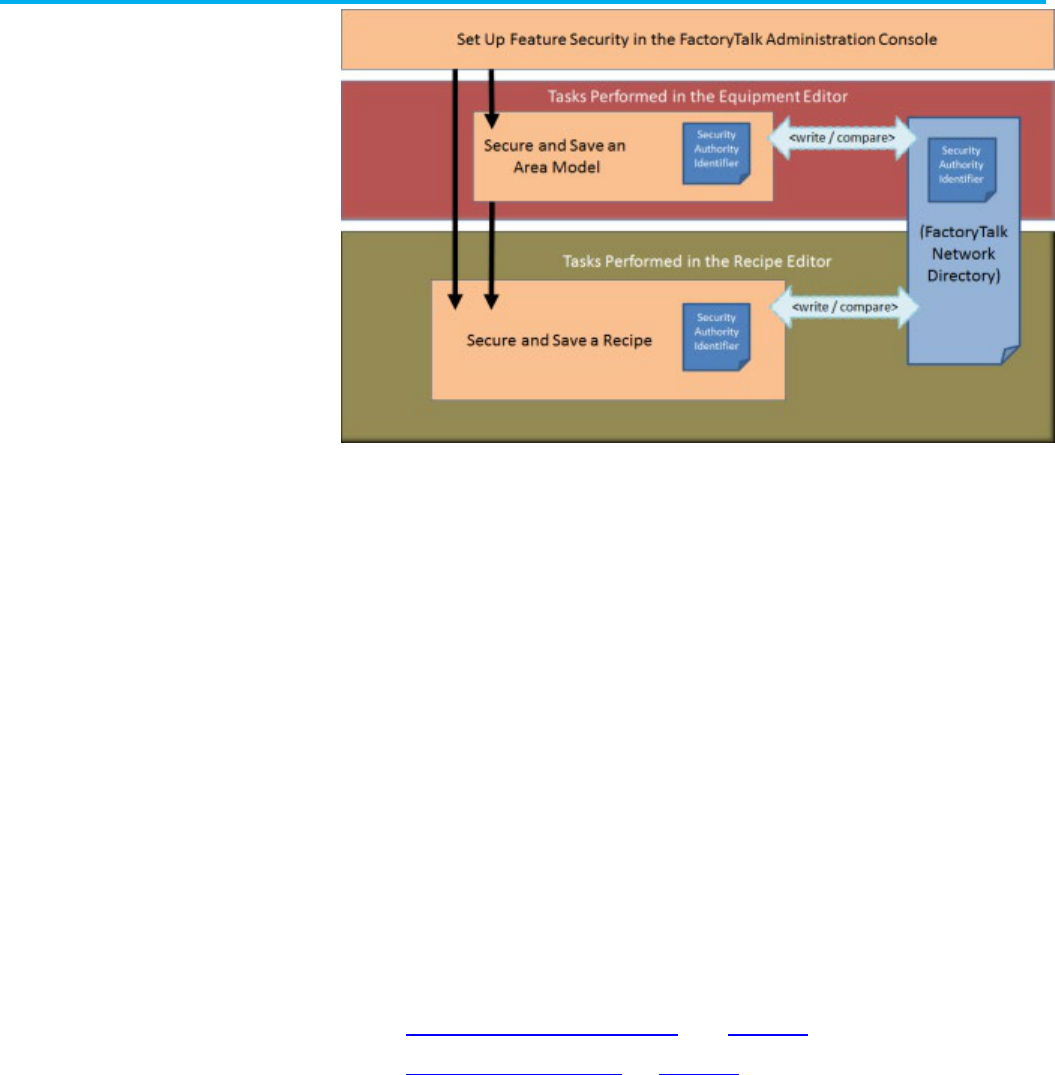
Chapter 8 Security authority overview
80 Rockwell Automation Publication BATCH-UM004C-EN--D - November 2023
Authority to secure area models and recipes is assigned in the
FactoryTalk Administration Console. Security Authority is disabled by
default.
Area models are secured within FactoryTalk Batch Equipment Editor
using the Security Authority command. The FactoryTalk Network
Directory Security Authority Identifier (SAI) is written into the area model
schema. To subsequently open and edit the area model, the SAI in the
area model must match that of the current FactoryTalk Network
Directory. No match prevents the opening and editing of an area model
and its associated recipes in FactoryTalk Batch Recipe Editor.
Recipes are secured within FactoryTalk Batch Recipe Editor using the
Security Authority command. The FactoryTalk Network Directory SAI is
written into the recipe header data. To subsequently open and edit the
recipe in FactoryTalk Batch Recipe Editor, the SAI in the recipe must
match the one in the current FactoryTalk Network Directory.
Import and export operations with secured recipes are restricted.
See also
Security authority overview on page 79
Secure an area model on page 80
Area models are secured using the Security Authority command.
To secure an area model:
1. Select Start > Rockwell Software > Equipment Editor.
2. Open the area model to secure.
Secure an area model

Chapter 8 Security authority overview
Rockwell Automation Publication BATCH-UM004C-EN--D - November 2023 81
IMPORTANT
Before securing an area model to a specific FactoryTalk Network Directory,
Rockwell Automation recommends backing up the FactoryTalk Network
Directory and storing unsecured versions of the area model file in configuration
(.cfg), XML (.axml), or text (.txt) formats in a secure location.
For backup details, see FactoryTalk Help: Select
Start > Rockwell Software >
FactoryTalk Tools FactoryTalk Help
.
Once an area model is secured with a particular FactoryTalk Network Directory,
the area model cannot be opened if the security authority identifier associated
with that directory no longer exists.
3. Select Edit > Security Authority. The Security Authority dialog
box opens.
4. Select the check box to secure the area model. If the check box is
not enabled, the logged in user account is not authorized to use
this feature.
5. Select OK.
See also
Security authority overview on page 79

Rockwell Automation Publication BATCH-UM004C-EN--D - November 2023 83
Chapter 9
Data servers overview
A FactoryTalk Batch data server is a system object that is a reference to
an OPC, FactoryTalk Linx FactoryTalk Live Data, or Common Industrial
Protocol (CIP) data server program and one of its associated data
sources. These data server references provide run-time information from
the process-connected device (PCD) to FactoryTalk Batch View or the
HMI software. Data servers are used to pass data between the
FactoryTalk Batch Server and the PCD. Configure a separate
FactoryTalk Batch data server for each data source, and its associated
data server program, that communicates with the FactoryTalk Batch
Server.
In FactoryTalk Batch Equipment Editor, add a data server definition for
each data server program (and its associated data source) that
communicates with the FactoryTalk Batch Server. This allows
FactoryTalk Batch to access current tag data within the PCD, which is
necessary to successfully run recipes, arbitrate equipment, and control
single phases or operation sequences.
Tip: The FactoryTalk Linx FactoryTalk Live Data protocol is based on the OPC Data Access protocol.
The FactoryTalk Batch Simulator imitates the functionality of a data server and can communicate
with the FactoryTalk Batch Server using OLE for Process Control (OPC) communications. Sample
programs are included with the FactoryTalk Batch Phase Simulator and can be run to simulate batch
processes without being connected to a PCD.
See also
Area model data servers on page 83
OPC data servers on page 86
A minimum of one data server needs to be defined in the area model.
Define a data server before adding phases or operation sequences to
the area model.
IMPORTANT
The Instruction-Based Server is for use with FactoryTalk eProcedure only. The data
server automatically creates when an area model opens. A new data server using the
InstructionBasedServer data server type cannot be created. If this data server is
deleted, any phases or operation sequences and associated tags are also deleted. The
next time the area model opens, the data server automatically creates again.
FactoryTalk Batch supports these data server protocols:
• OPC Data Access protocol
• FactoryTalk Live Data protocol
• Common Industrial Protocol (CIP)
The Data Servers dialog box provides a list of data servers defined for
the active area model. When you create a phase or operation and
multiple Data Servers are listed, the first data server in this list is the
Area model data servers

Chapter 9 Data servers overview
84 Rockwell Automation Publication BATCH-UM004C-EN--D - November 2023
default. Select the Name header to sort the list in ascending or
descending alphabetical order.
See also
Data Servers dialog box on page 84
The Data Servers dialog box contains:
Name
Purpose
Name The user-defined name of the data server. Select the
Name
header to sort the
data servers in ascending or descending alphabetical order.
Type
The type of data server, defined by a DSDF file. By selecting the Type header,
the data server
types
can be sorted in ascending or descending alphabetical
order.
Add
Opens the Add Data Server dialog box that is used to add new data servers to
the area model.
Edit
Opens the Edit Data Server dialog box that is used to edit existing data servers.
Remove
Opens the Remove Data Server dialog box that is used to remove an existing
data server. The dialog box displays a list of all associated phases or operation
sequences, phase tags or operation sequence tags, and unit attribute tags that
are removed.
Close
Closes the dialog box without applying a data server selection.
See also
Area model data servers on page 83
When editing an OPC or FactoryTalk® Linx FactoryTalk Live Data server
associated with a unit attribute tag, a phase or any tag within a phase,
Logix5000 CIP does not display in the Type list. One OPC type can be
changed to another or changed from an OPC type to a FactoryTalk Linx
FactoryTalk Live Data type (for example, for a Simulator OPC data
server, change Type to Rockwell FactoryTalk Linx OPC), but an OPC
or FactoryTalk Linx FactoryTalk Live Data type server cannot be
changed to a Logix5000 CIP type data server.
To change the Type to Logix5000 CIP, delete the data server, and add a
new one.
Data Servers dialog box
Edit a data server

Chapter 9 Data servers overview
Rockwell Automation Publication BATCH-UM004C-EN--D - November 2023 85
IMPORTANT
When using FactoryTalk Linx with a Live Data/OPC data server, the following entry must
be added to the FTLX.dsdf in the \Batch\DataServers folder:
ForceBoolTrueToOne=YES
This is also required when updating from RSLinx Classic to FactoryTalk Linx.
To edit a data server:
1. Select Start > Rockwell Software > Equipment Editor.
2. Select Edit > Data Server to open the Data Servers dialog box.
3. Select the data server definition edit, and then select Edit.
The Edit Data Server dialog box opens.
4. Make any required changes and select OK to return to the Data
Servers dialog box.
All phase tags assigned to the modified data server definition are
updated to reflect the changes.
5. Close the Data Servers dialog box.
See also
OPC data servers on page 86
Delete a data server on page 85
Use these instructions to delete a data server.
To delete a data server:
1. Select Start > Rockwell Software > Equipment Editor.
2. Open the Data Servers dialog box.
3. Select the data server to delete, and then select Remove.
• If the data server is not assigned to any phases or operation
sequences, this message displays:
• If the data server is assigned to any phases, operation
sequences, or unit attribute tags, the Remove Server dialog
box opens. All the phases, operation sequences, and unit
attribute tags associated with the data server are listed.
Tip: The displayed phases or operation sequences and all of their tags, as well as the
displayed unit attribute tags, are deleted when the data server is removed.
4. Perform one of the following steps:
• To delete the data server and remove all associated phases or
operation sequences and tags, select Yes.
• To cancel the deletion and return to the Data Servers dialog
box, select No.
5. Close the Data Servers dialog box.
Delete a data server

Chapter 9 Data servers overview
86 Rockwell Automation Publication BATCH-UM004C-EN--D - November 2023
See also
Assign data servers on page 86
After a data server is added, assign it to either a phase, an operation
sequence, or a unit.
Phase or operation sequence
Unit
Assign a data server to a phase or operation
sequence to link the equipment piece to the
specified controller.
Assign the same data server to all phases or
operation sequences subsequently created in a
unit. Select the data server in the
Edit Unit
dialog
box.
See also
Configure the general data for a process cell on page 107
Data servers overview on page 83
These items are displayed for OPC data servers.
When adding a data server to the area model, these items must be
configured in the Add Data Server dialog box:
Name
Purpose
Name
The unique user-defined name for the data server definition.
Type
The various choices of data server types are defined within separate DSDF
files.
Default Item Access Path
The OPC item access path that is the default for the tags on all
subsequently created phases that this data server is assigned to.
To reset the access path for all phase tags to this value, in the
Edit Phase
dialog box
Tags
tab, select
Defaults
. The tag item names are also reset to
include the name of the phase.
Watchdog Item Access Path
The OPC watchdog item access path is for data servers that do not require
separate read and write items. For data servers that require separate read
and write items, this label changes to
Watchdog Read Item Access Path
and
is used only for the read item access path. This is optional, depending on
the data server.
Watchdog Item Name
The name of the OPC watchdog item for data servers that do not require
separate read and write items. For data servers that require separate read
and write items, this label changes to
Watchdog Read Item Name
and is
used only for the read item name.
Location
Only used with OPC data servers. The location of the OPC data server. If the
data server is located on the local computer,
Local
must be selected. If the
data server is located on a remote network computer,
Remote
must be
selected and the name of the computer where the data server is located
must be provided. Enter the name of the remote computer using the
naming scheme of the network transport. By default, Universal Naming
Convention (UNC) names and Domain Names System (DNS) names are
supported.
FactoryTalk Linx Server Path
Only used with FactoryTalk Linx FactoryTalk Live Data servers. A string that
defines the path to a data server located in the FactoryTalk Directory. (See
FactoryTalk Linx Live Data server for more information.)
Watchdog Protocol
The type of watchdog protocol to be used by the data server. This can be
either the Standard or Enhanced protocol.
Watchdog Write Item Access
Path
The OPC access path for the watchdog write item. If the data server does
not require separate read and write items or does not require an access
path, this is disabled.
Watchdog Write Item Name The OPC item name for the watchdog write item. If the data server does not
require separate read and write items, this is disabled.
Assign data servers
OPC data servers

Chapter 9 Data servers overview
Rockwell Automation Publication BATCH-UM004C-EN--D - November 2023 87
Name
Purpose
Scan Rates
The default On Control and Off Control scan rates for the data server, in
milliseconds. The valid range of the
On Control
scan rate is 250 through
30,000 milliseconds. The valid range of the
Off Control
scan rate is 250
through 60,000 milliseconds. The usage of these rates is determined by the
type of data server selected. Typically, these values do not need to be
modified.
See also
FactoryTalk Linx FactoryTalk Live Data server on page 88
These instructions only apply to OPC data servers.
Tip: When using FactoryTalk Linx with a Live Data/OPC data server, the following entry must be added
to the RSLinxEnterprise.dsdf in the \Batch\DataServers folder:
ForceBoolTrueToOne=YES
This is also required when updating from RSLinx Classic to FactoryTalk Linx.
To add an OPC data server:
1. Select Start > Rockwell Software > Equipment Editor.
2. Select Edit > Data Server. The Data Servers dialog box opens.
3. Select Add.
4. In Name, type a name for the data server.
5. From Type, select the data server definition that corresponds to
the physical OPC data server being defined.
6. If necessary, type the appropriate values for the Default Item
Access Path, Watchdog Item Access Path, and Watchdog
Item Name.
7. Under Location, select the appropriate option. If Remote is
selected, type the remote data server name.
8. Select More. Additional options display.
9. Under Watchdog Protocol, select either the Standard or
Enhanced protocol.
10. If necessary, type the appropriate values for the Watchdog
Write Item Access Path and the Watchdog Write Item Name.
Add an OPC data server

Chapter 9 Data servers overview
88 Rockwell Automation Publication BATCH-UM004C-EN--D - November 2023
11. Under Scan Rates, type the On Control and Off Control scan
rates for the data server.
12. Select OK to save the data server configuration and return to
the Data Servers dialog box.
See also
OPC data servers on page 86
The FactoryTalk Linx FactoryTalk Live Data protocol provides services
that read and write real-time manufacturing data from OPC servers and
controllers for all participating FactoryTalk-enabled products in the
FactoryTalk Directory. FactoryTalk Live Data improves on OPC-Data
Access (DA) by making communication with multiple servers easier.
To support FactoryTalk Batch as a FactoryTalk Live Data client,
FactoryTalk Linx must be part of the FactoryTalk system. FactoryTalk
Linx is a communication server that provides plant-floor device
connectivity for Rockwell Automation applications and Logix processors.
See also
Add a data server on page 88
FactoryTalk Linx server path on page 90
Configure the FactoryTalk Linx server path on page 90
The items necessary to configure a FactoryTalk® Live Data data server
in FactoryTalk Batch Equipment Editor are identical to OPC servers with
the exception of the FactoryTalk Linx server path.
Before you begin:
Complete these prerequisites:
FactoryTalk Linx
FactoryTalk Live Data
server
Add a data server

Chapter 9 Data servers overview
Rockwell Automation Publication BATCH-UM004C-EN--D - November 2023 89
• Install and configure FactoryTalk Linx. (For more information, refer
to FactoryTalk Linx Help.)
• Create an Application in the FactoryTalk Directory. (For more
information, refer to FactoryTalk Help located in the FactoryTalk
Administration Console.)
• Add a FactoryTalk Linx data server to the FactoryTalk Application.
Adding a data server to an application provides a link between a
hardware device containing tags and the FactoryTalk Directory.
(For more information, refer to FactoryTalk Help located in the
FactoryTalk Administration Console.)
To add a data server:
1. Select Start > Rockwell Software > Equipment Editor.
2. Select Edit > Data Serve FactoryTalk Batch Suite >
FactoryTalk Batch, and then select r to open the Data Servers
dialog box.
3. Select Add to open the Add Data Server dialog box.
4. In Name, type a name for the data server.
5. From Type, select FactoryTalk Linx. When the data server Type
is FactoryTalk Linx, the FactoryTalk Linx Server Path text box
replaces the Location text box in the Add Data Server dialog
box.
6. If necessary, type the appropriate values for the Default Item
Access Path and the Watchdog Item Access Path. (These are
the device shortcut name(s) assigned in FactoryTalk Linx
FactoryTalk Live Data.)
7. If necessary, type the appropriate values for the Watchdog Item
Name.
8. Type the connection string for the FactoryTalk Linx Server Path
found on the FactoryTalk Administration Console dialog box.
Enter the path that is shown, but without the server name shown at

Chapter 9 Data servers overview
90 Rockwell Automation Publication BATCH-UM004C-EN--D - November 2023
the end of the path. (See FactoryTalk Linx path for more
information.)
9. Select More to view the watchdog write item access path and
name and the on and off control scan rates for the data server.
10. Select OK to save the data server configuration and return to
the Data Servers dialog box.
See also
FactoryTalk Linx server path on page 90
Once a FactoryTalk Linx data server is added to an Application in the
FactoryTalk Directory, to view the FactoryTalk Linx Server Path
connection string that is needed to configure the FactoryTalk Linx server
type in FactoryTalk Batch Equipment Editor, see the Communication
Setup title in the Communication Setup dialog box.
In this example, the FactoryTalk Linx Server Path connection string is:
RNA://$Global/MyApplication/
(Note that the final name in the path (FactoryTalk Linx) does not show at
the end as shown in the image.)
See also
Configure the FactoryTalk Linx server path on page 90
Use these instructions to open the FactoryTalk Communication Setup
dialog box.
To configure the FactoryTalk Linx server path:
1. Open the FactoryTalk Administration Console and log on to the
appropriate FactoryTalk Directory.
2. Point to MyApplication > FactoryTalk Linx > Communication
Setup.
3. Right-click Communication Setup and select Open.
The Communication Setup dialog box opens. The FactoryTalk
Linx Server Path connection string displays as part of the title.
FactoryTalk Linx server
path
Configure the FactoryTalk
Linx server path

Chapter 9 Data servers overview
Rockwell Automation Publication BATCH-UM004C-EN--D - November 2023 91
See also
FactoryTalk Linx FactoryTalk Live Data server on page 88
Configure the Logix5000 CIP data server in FactoryTalk Batch
Equipment Editor to use PhaseManager features. To configure the
FactoryTalk Batch system with PhaseManager, add a Logix5000 CIP
data server and assign it to PhaseManager phases. After these
configuration tasks are completed, automatically create the FactoryTalk
Batch phases in the Logix Designer project file by synchronizing the area
model with the project file.
See also
Add a Logix5000 CIP data server on page 91
Assign a Logix5000 CIP data server to a phase or sequence on
page 93
Add data servers either before creating the rest of the elements in the
area model, or after defining the process cells, unit classes, phase
classes, operation sequence classes, and resources in the area model.
Define at least one data server before creating the specific phases from
the phase classes or specific operation sequences from the operation
sequence classes.
If possible, create the project file in Logix Designer before adding a
Logix5000 CIP data server. Specify the project file when adding a
Logix5000 CIP data server to detect errors more easily when designing
the system.
Prerequisites
• Configure device shortcuts in the FactoryTalk Administration
Console for all controllers that FactoryTalk Batch communicates
with PhaseManager or SequenceManager objects.
• Install and configure FactoryTalk Linx. (For more information, refer
to FactoryTalk Linx Help.)
• Create an Application in the FactoryTalk Directory. (For more
information, refer to FactoryTalk Help in the FactoryTalk
Administration Console.)
• Add a FactoryTalk Linx data server to the FactoryTalk Application.
Adding a data server to an application provides a link between a
hardware device containing tags and the FactoryTalk Directory.
(For more information, refer to FactoryTalk Help in the FactoryTalk
Administration Console.)
To add a Logix5000 CIP data server
1. Select Start > Rockwell Software > Equipment Editor.
2. Select Edit > Data Server to open the Data Servers dialog box.
3. Select Add to open the Add Data Server dialog box.
4. In the Name box, type a name for the data server.
Logix5000 CIP data server
Add a Logix5000 CIP data
server

Chapter 9 Data servers overview
92 Rockwell Automation Publication BATCH-UM004C-EN--D - November 2023
Tip: The name should easily identify the Logix 5000 controller that this data server
represents. Using the type of Logix 5000 controller and its location in the chassis as the
name, or the unit that this controller connects to in the plant as the name, may help to easily
identify the controller.
When synchronizing the area model with the Logix Designer project, this name displays in the
Synchronize Logix5000 Data Servers
dialog box. Choose which data server to synchronize by
selecting the name.
5. Select Logix5000 CIP for the Type.
6. (optional) To create phases or operation sequences in the area
model before completing the remaining information in this dialog
box, select OK to close this dialog box. Finish adding information
about the data server later.
7. To enable synchronization between the .acd file and the area
model, select Browse, navigate to a project .acd file that contains
the phase for the controller this data server represents. The file's
revision and controller type display in the boxes.
Tip: The Logix Designer project file must be revision 16.0 or higher.
To resolve any error messages that appear when selecting a project file, see
Select a project
file - error messages.
8. In the FactoryTalk Linx Controller Shortcut box, select Browse
to locate the device shortcut for communicating with the specified
controller.
Alternatively, type the path to the shortcut using this format:
RNA://Global/UsersApplicationName/FTLinxAreaName/Fa
ctoryTalkLinx/ShortcutName
9. (optional) Select More to display the Timeout and Retries boxes.
10. The default values are the recommended settings for these
boxes. Adjust these values for the speed of the network.
Name
Value
Timeout
How often the FactoryTalk Batch Server attempts to contact the controller. The range of
valid values is 500 milliseconds to 100000 milliseconds. The default is 8000
milliseconds.
Retries
The number of times the FactoryTalk Batch Server tries to contact the controller before
dropping the connection. The valid values appear in the list. The default is 4.
Timeout * Retries = Length of time the FactoryTalk Batch Server attempts to contact the controller before
losing the connection.
11. Select OK to close the Add Data Server dialog box.
12. Select OK to close the Data Servers dialog box.
See also
Edit a Logix5000 CIP data server on page 92
Use these instructions to edit a Logix5000 CIP data server.
To edit a Logix5000 CIP data server:
1. Select Edit > Data Server. The Data Servers dialog box opens.
2. Select the data server definition to be edited, and select Edit. The
Edit Data Server dialog box opens.
3. Make any required changes and select OK to return to the Data
Servers dialog box.
Edit a Logix5000 CIP data
server

Chapter 9 Data servers overview
Rockwell Automation Publication BATCH-UM004C-EN--D - November 2023 93
Tip: After adding a data server as a Logix5000 CIP type data server, the type cannot change.
No other data server types appear in the
Type
selection list when editing. To change the
Type
,
delete the data server and add a new one.
4. (optional) To delete a data server, select the data server to delete
and select Remove.
• If the data server is not assigned to any phases, this message
displays:
• If the data server is assigned to phases, the Remove Server
dialog box opens, displaying these phases and unit tags
associated with the data server.
The displayed unit tags and phases, as well as their parameter,
report, and limit tags are deleted when the data server is
removed.
• Select Yes to delete the data server and remove all associated
phases and tags.
See also
Assign a Logix5000 CIP data server to a phase or sequence on
page 93
After adding a Logix5000 CIP data server, assign it to each phase or
sequence that represents a piece of equipment connected to the
controller specified in the controller network path of the Logix5000 CIP
data server.
To assign a Logix5000 CIP data server to a phase or sequence:
1. Select Start > Rockwell Software > Equipment Editor.
2. Select the phase or sequence icon in the Design View area and
select Edit > Properties. The Edit Phase dialog box, General tab
displays.
3. From the Data Server list, select the Logix5000 CIP data server
that represents the controller connected to the piece of equipment
defined by this phase or sequence.
4. Select OK.
See also
Edit a Logix5000 CIP data server on page 92
Assign a Logix5000 CIP data
server to a phase or
sequence

Rockwell Automation Publication BATCH-UM004C-EN--D - November 2023 95
Chapter 10
Resources overview
Resource is a general term for equipment including process cells, units,
phases and shared control modules.
Define the resources in the area model before assigning them as shared
equipment. Create resource classes (such as PUMPS) and resource
instances (such as PMP102). After resource instances are defined in the
area model, they can be assigned to process cells, units, phases, and
other resources as necessary equipment that is allocated by the
FactoryTalk Batch Server. To configure a resource instance, assign a
name, equipment ID, the maximum number of owners, and any other
equipment requirements for that resource. When the maximum number
of owners are defined, the number of area model components that can
simultaneously use the resource are also defined.
Resources can be simultaneously owned by one or more area model
components, depending on the program. For example, if a pump is
physically configured to charge an ingredient into three different vessels
but it has the capacity to charge only two of the three vessels
simultaneously, define the pump as a shared resource and specify the
maximum number of owners as 2.
See also
View and manage system elements from the Diagnostics page on
page 95
When you need to have an overall view or to manage system elements
for an area, use Diagnostics > Arbitration.
Diagnostics > Arbitration provides a method for displaying arbitration
information from different perspectives. System elements have a limited
number of owners based on their definition in the area model. System
elements are acquired when they are not currently owned, or the number
of current owners is fewer than the defined maximum number of owners.
Only the current owner can release a system element.
See also
Arbitration
View arbitration information from the Diagnostics page
Acquire a system element from the Diagnostics page
Release a system element from the Diagnostics page
Reorder the Needed By queue from the Diagnostics page
Manage Diagnostics page
system elements

Chapter 10 Resources overview
96 Rockwell Automation Publication BATCH-UM004C-EN--D - November 2023
Use these instructions to define shared resources.
To define shared resources:
1. Select Start > Rockwell Software > Equipment Editor.
2. Select Edit > Resources.
3. To create a new resource class, select Add Class. The Edit
Resource Class dialog box displays.
d. In Name, type the new resource class name.
e. Select OK to return to the Edit Resources dialog box. The
new resource class displays in the Resource Classes
column.
4. To add a resource instance to a resource class, select the new
resource class, and then select Add. The Edit
Resources: [Resource Name] dialog box displays.
The Edit Resources: [Resource Name] dialog box contains four
tabs:
• General
• Arbitration
• Cross Invocation
• Hyperlink (eProcedure only)
See also
Configure general information for resources on page 96
Configure arbitration information for resources on page 97
Configure cross invocation information for resources on page 98
Configure hyperlink information for resources on page 98
Use these instructions to configure general information.
1. Select Start > Rockwell Software > Equipment Editor.
2. Select Edit > Resources.
3. Under Resources, select the resource and then select Edit.
4. In the Edit Resources: [Resource Name] dialog box, select the
General tab.
5. In Name, type the resource name (for example, Pump101,
PV203).
Define shared resources
Set general information for
resources

Chapter 10 Resources overview
Rockwell Automation Publication BATCH-UM004C-EN--D - November 2023 97
6. Type the appropriate Equipment ID, or accept the default ID.
7. Select Apply to save changes and continue, or select OK to return
to the Edit Resources dialog box.
See also
Define shared resources on page 96
Configure arbitration information for resources on page 97
Configure cross invocation information for resources on page 98
Configure hyperlink information for resources on page 98
In the Edit Resources dialog box Arbitration tab, the Equipment
Allocation by Resource area contains a hierarchical view in the left
pane that displays the current equipment configuration of the area
model. The hierarchy has two roots: Process Cells and Resources. The
right pane is the list of equipment on which this resource is dependent.
Any equipment in the right pane must be acquired by the FactoryTalk
Batch Server before any procedural element requiring this resource can
begin execution.
Expand the Process Cells root to view all the process cells within the
area model. From here, organization is hierarchical, so process cells
contain units and units contain phases.
Expand the Resources root to view a list of all the configured resource
instances within the area model.
1. Select Start > Rockwell Software > Equipment Editor.
2. Select Edit > Resources.
3. Under Resources, select the resource and then select Edit.
4. In the Edit Resources: [Resource Name] dialog box, select the
Arbitration tab.
5. In Max Owners, enter the number that represents how many
process cells, units, phases, or other resources can maintain
ownership of this resource at one time.
6. Under Equipment Allocation by Resource, browse the area
model’s equipment hierarchy to specify equipment this resource
needed. A plus sign (+) to the left of the equipment type indicates
equipment of that type has been defined.
• To add equipment to the right pane, select the equipment
needed by the resource in the left pane and select Add. The
equipment this resource needs to acquire displays in the right
pane.
• To remove equipment, in the right pane, select the equipment to
delete and select Remove. The selected equipment is removed
from the list.
7. Select Apply to save changes and continue, or select OK to return
to the Edit Resources dialog box.
See also
Define shared resources on page 96
Configure arbitration
information

Chapter 10 Resources overview
98 Rockwell Automation Publication BATCH-UM004C-EN--D - November 2023
Configure general information for resources on page 96
Configure cross invocation information for resources on page 98
Configure hyperlink information for resources on page 98
Use the Cross Invocation tab to specify cross invocation labels for
different resource types.
1. Select Start > Rockwell Software > Equipment Editor.
2. Select Edit > Resources.
3. Under Resources, select the resource and then select Edit.
4. In the Edit Resources: [Resource Name] dialog box, select the
Cross Invocation tab.
5. In Cross Invocation Label #, type the cross invocation string
contents information.
6. Select Apply to save changes and continue, or select OK to save
changes and return to the Edit Resources: [Resource Name]
dialog box.
See also
Configure hyperlink information for resources on page 98
This feature, allows hyperlinks to be associated with any of the
equipment resources, used in conjunction with eProcedure only.
1. Select Start > Rockwell Software > Equipment Editor.
2. Select Edit > Resources.
3. Under Resources, select the resource and then select Edit.
4. If hyperlinks are being used, in the Edit Resources: [Resource
Name] dialog box, select the Hyperlink tab.
5. In Hyperlink Label # English, type a valid URL string.
6. Select Apply to save changes and continue, or select OK to return
to the Edit Resources: [Resource Name] dialog box.
7. When finished creating the shared resources, select OK to return
to the Design View area.
See also
Define shared resources on page 96
Configure general information for resources on page 96
Configure arbitration information for resources on page 97
Configure cross invocation information for resources on page 98
Set cross invocation
information
Configure hyperlink
information

Rockwell Automation Publication BATCH-UM004C-EN--D - November 2023 99
Chapter 11
Global binding requirements
Global unit binding requirements are sets of expressions that tell the
FactoryTalk Batch Server what units are valid binding candidates for a
recipe. A binding requirement can be evaluated against instances of a
unit class to determine which instances of the class are legal bind
candidates for a unit requirement. When the FactoryTalk Batch Server
attempts to bind a unit requirement during recipe execution, the entire set
of binding requirements defined for the unit requirement is evaluated
against each potential binding candidate. Units unable to meet every
binding requirement defined for the unit requirement are eliminated as
potential binding candidates.
A global binding requirement is automatically applied to every unit
requirement within a recipe. Pre-configuring global binding requirements
in an area model, and then loading that area model within FactoryTalk
Batch Recipe Editor, eliminates having to manually add the binding
requirement to every unit requirement in every recipe.
For example, a global binding requirement may be
Days_since_CleanInPlace < 3. This binding requirement might be
imposed by corporate quality standards. This means that no unit is
considered acceptable for use unless it has been cleaned within the last
three days. As a global unit requirement, this requirement is required to
be applied against every unit requirement in the plant.
See also
Unit binding expression builder on page 99
Create global binding requirements on page 102
Create expressions in the Unit Binding Expression Builder. The Unit
Binding Expression Builder contains a type list on the left pane, which
displays Recipe Header and Unit Attribute data that can be used to build
an expression.
When Recipe Header is selected, a list of recipe header parameters
displays in the list view (in the middle). The Recipe Header box names
map to the same boxes defined in FactoryTalk Batch Recipe Editor within
a Recipe Header.
When the Unit Attributes is selected, an alphabetic list of all global unit
attributes existing within the area model displays in the list view.
Create or edit an expression by typing directly in the Expression Builder
text box, selecting items in the list view and enumerations view, selecting
various operators, or selecting a combination of items and operators. The
Operator buttons of the Expression Builder are always enabled. When
an Operator button is selected, the corresponding operator is inserted
Unit binding expression
builder

Chapter 11 Global binding requirements
100 Rockwell Automation Publication BATCH-UM004C-EN--D - November 2023
into the expression at the current cursor position and displays in the
Expression Builder text box.
See also
Create a global unit attribute on page 132
Expression operators on page 100
Supported data types on page 101
Operands on page 102
Expression validation on page 102
Binding expressions support operators. The precedence of the execution
depicts from highest to lowest. An operator with a higher precedence
executes before an operator of lower precedence.
Expression Operator
Purpose
( )
Expressions within parentheses are evaluated before expressions outside
of parentheses.
NOT, -
Logical NOT, subtraction.
*, / , AND
Multiplication, division, and logical AND.
+, -, OR
Addition, subtraction, and logical OR.
<, <=, >, >=
Less than, less than or equal to, greater than, and greater than or equal to.
=, < >
Equal to, and not equal to.
See also
Unit binding expression builder on page 99
Supported data types on page 101
Expression operators

Chapter 11 Global binding requirements
Rockwell Automation Publication BATCH-UM004C-EN--D - November 2023 101
Operands on page 102
Expression validation on page 102
The data types supported are integer, real, string, and enumeration.
Unsigned data types introduced in Logix5000 version 32.00 are not supported by FactoryTalk Batch.
Configuring a FactoryTalk Batch tag to reference a controller tag of any unsigned data type (USINT,
UINT, UDINT, ULINT) will result in bad communication. If you attempt to run batches referencing any
tags that include one of these data types a communication failure occurs at the point when the tag is
used.
Use FactoryTalk Batch Tag Verify to produce a report that identifies any issues with the tag(s).
Supported data type examples:
Integer: 423
Real: 423.123456789012
String: The string constant must be in quotes: "READY".
Enumeration: As a string, the enumeration constant must be in quotes:
"BUTTER_PECAN". As an integer, the ordinal for the enumeration may
be: 4.
See also
Unit binding expression builder on page 99
Operands on page 102
Expression validation on page 102
Supported data types

Chapter 11 Global binding requirements
102 Rockwell Automation Publication BATCH-UM004C-EN--D - November 2023
Operands
Operands used within a global unit binding expression can reference
recipe header data, global unit attributes, and constants.
Examples of allowable expression entities and the required syntax:
Expression Entity
Expression Syntax
Example
Recipe header data
[Recipe header item]
[VERSION_NUMBER]
Global unit attribute
Unit attribute name
CAPACITY
Constant
100
See also
Unit binding expression builder on page 99
Although an invalid expression cannot be created, a previously valid
expression may become invalid through subsequent changes elsewhere
in the area model. When the Edit Global Unit Binding Requirements
dialog box is invoked all binding expressions are re-validated. If any
current expressions have become invalid due to subsequent changes, an
error message opens and the dialog displays an asterisk beside each
invalid expression.
The expression validates for consistency and syntactical correctness. If
the defined expression validates successfully, the dialog box closes. If
the expression is invalid, then the location of where the first error
encountered highlights, a description of the error displays in a message
box, and the dialog box does not close.
Validation rules:
• An expression must resolve to either TRUE or FALSE and meet
the criteria:
• An expression must contain at least one operator (+ (addition), -
(subtraction), * (multiplication), / (division), = (equals), > (greater
than), < (less than), <= (less than, or equal to), >= (greater than,
or equal to), <> (not equal to), Not, And, and Or.
Tip:
OR transitions fire if at least one side of the expression is TRUE.
• Separate each entity (recipe header, global unit attribute, or
constant) with an operator.
• The operated entities must evaluate to acceptable data types
(string with a string; integer with integer or real; real with integer
or real).
• Maximum expression length must not exceed 1023 characters.
• Duplicate expressions are allowed.
Use these instructions to create global binding requirements.
Expression validation
Create global binding
requirements

Chapter 11 Global binding requirements
Rockwell Automation Publication BATCH-UM004C-EN--D - November 2023 103
To create global binding requirements:
1. Select Start > Rockwell Software > Equipment Editor.
2. Select Edit > Global Binding Requirements.
3. Select Add Requirement.
4. In the Unit Binding Expression Builder dialog box, select
options from the three different sections or type to build an
expression.
Tip: A binding requirement expression evaluates to either a TRUE or FALSE value,
TEMPERATURE < 20.3, for example.
5. Select OK to save the expression and return to the Edit Global
Unit Binding Requirements dialog box.
6. Continue building more binding requirements, or select OK to exit
the dialog box.
See also
Unit binding expression builder on page 99
Expression validation on page 102
Edit binding requirements on page 103
Delete binding requirements on page 104
Use these instructions to edit binding requirements:
To edit binding requirements:
1. Select Start > Rockwell Software > Equipment Editor.
Edit binding requirements

Chapter 11 Global binding requirements
104 Rockwell Automation Publication BATCH-UM004C-EN--D - November 2023
2. Select Edit > Global Binding Requirements.
3. Select browse ( ) next to the requirement to edit.
4. Make the desired changes, and then select OK.
5. Select OK to close the Edit Global Unit Binding Requirements
dialog box.
See also
Create global binding requirements on page 102
Delete binding requirements on page 104
Use these instructions to delete binding requirements.
To delete binding requirements:
1. Select Start > Rockwell Software > Equipment Editor.
2. Select Edit > Global Binding Requirements.
3. Select Delete Requirement, and then select OK to confirm the
deletion or Cancel to keep the requirement.
4. Select OK to close the Edit Global Unit Binding Requirements
dialog box.
See also
Create global binding requirements on page 102
Edit binding requirements on page 103
Delete binding
requirements

Rockwell Automation Publication BATCH-UM004C-EN--D - November 2023 105
Chapter 12
Process cell overview
A process cell is a logical grouping of equipment, including units,
required for the production of one or more batches. It can contain more
than one grouping of equipment if more than one grouping is needed to
make a batch. Process cells are grouped into classes. For each type of
process cell in a selected area, a process cell class must first be created.
Once the process cell class has been created, an instance of that class
can be created in the Design View area.
See also
Create a process cell class on page 105
Edit a process cell class on page 105
Create and configure process cell instances on page 106
Configure hyperlink data for a process cell on page 109
Use these instructions to create a process cell class.
Tip: If the icon column is empty, see Verify icon paths.
To create a process cell class:
1. Select Start > Rockwell Software > Equipment Editor.
2. In the Class View area, verify that the column heading is Cell
Classes. If not, select Go Up ( ) until the top level of the ar
ea
m
odel is shown.
3. Select Class > New Process Cell Class.
4. In Na
me, enter a name for the process cell class.
5. Under Icon, select an ic
on.
6. S
elect OK.
See also
Verify icon paths on page 111
Process cell overview on page 105
Use these instructions to edit a process cell class.
To edit a process cell class:
1. Select Start > Rockwell Software > Equipment Editor.
Create a process cell class
Edit a process cell class

Chapter 12 Process cell overview
106 Rockwell Automation Publication BATCH-UM004C-EN--D - November 2023
2. Select the process cell class to edit.
3. Select Edit > Properties. The Edit Process Cell Class dialog
box opens.
4. Make the desired changes, and then select OK to return to the
Class View area.
See also
Create and configure process cell instances on page 106
Verify icon paths on page 111
Unique icons on page 111
Use these instructions to create and configure process cell instances.
To create and configure process cell instances:
1. Select Start > Rockwell Software > Equipment Editor.
2. Select the desired process cell class.
The cursor changes to a c.
3. Place the cursor in the desired location in the Design View area
and select.
The process cell icon displays in the Design View area with a
default name of PROCESS_CELL# (where # is a sequentially
assigned number starting with 1).
See also
Configure a process cell instance on page 106
Use these instructions to configure a process cell instance.
To configure a process cell instance:
1. Select Start > Rockwell Software > Equipment Editor.
2. Select a process cell icon in the Design View area.
3. Select Edit > Properties.
The Edit Process Cell dialog box displays with the assigned
defaults. The Edit Process Cell dialog box contains four tabs:
• General
• Arbitration
• Cross Invocation
• Hyperlink (eProcedure only)
See also
Configure the general data for a process cell on page 107
Create process cell
instances
Configure a process cell
instance

Chapter 12 Process cell overview
Rockwell Automation Publication BATCH-UM004C-EN--D - November 2023 107
Use these instructions to configure the general data.
1. Select Start > Rockwell Software > Equipment Editor.
2. Select a process cell icon in the Design View area.
3. Select Edit > Properties.
4. In the Edit Process Cell dialog box, select the General tab.
5. In Name, type a process cell name.
6. In ERP Alias, type the SAP R/3 process cell name.
The ERP alias is the process cell name in SAP. It maps the
process cell from FactoryTalk Batch to SAP.
7. In Equipment ID, type the equipment ID, or accept the default
value.
8. Select Apply to save changes.
See also
Edit process cell dialog box - General tab on page 107
The General tab of the Edit Process Cell dialog box contains:
Name
Purpose
Name
The name of the process cell. (The default name is PROCESS_CELL#. The # is a
consecutive number starting with 1 that is assigned to each process cell as it is added
to an area.)
Icon
The icon selected for the process cell class (view-only).
Class
The name of the process cell class (view-only).
ERP Alias
The SAP name for the phase. The ERP alias maps the equipment module from
FactoryTalk Batch to SAP.
Equipment ID The equipment identification number identifies this process cell. (A default ID is
automatically assigned to the process cell, based on the next available sequential
number. The first item added to an area is assigned ID #1.) To request this process
cell, the equipment ID must be the same as the equipment ID that is used by the
phase logic.
See also
Configure the general data for a process cell on page 107
In the Equipment Allocation by Resource area, the left pane is a
hierarchical display of the current equipment configuration of the area
model. The hierarchy has two roots: Process Cells and Resources. The
right pane is the list of equipment this process cell is dependent upon.
Any equipment in this list must be acquired by the process cell before any
procedural element linked to this process cell can begin execution.
Expand Process Cells to view all the process cells defined within the
area model. From here, organization is hierarchical; process cells contain
units and units contain phases.
Expand Resources to view a list of all the configured resources within
the area model.
1. Select Start > Rockwell Software > Equipment Editor.
2. Select a process cell icon in the Design View area.
3. Select Edit > Properties.
4. In the Edit Process Cell dialog box, select the Arbitration tab.
Set general data for a
process cell
General tab of Edit process
cell
Set arbitration data for
process cell

Chapter 12 Process cell overview
108 Rockwell Automation Publication BATCH-UM004C-EN--D - November 2023
5. In Max Owners, type the maximum number of owners.
6. Browse the area models equipment hierarchy to specify
equipment the process cell must acquire. The lack of a plus or
minus sign to the left of an equipment type indicates no equipment
of that type has been defined, or the equipment type cannot be
used as a needed equipment item at this level.
• To add equipment, under the Equipment Allocation by
Resource area, select the equipment needed by the process
cell and select Add. The selected equipment displays in the
right pane.
• To remove equipment, in the right pane, select the equipment to
delete and select Remove. The selected equipment is removed
from the list.
7. Select Apply to save changes.
See also
Edit Process Cell dialog box - Arbitration tab on page 108
The Edit Process Cell dialog box on the Arbitration tab contains:
Name
Purpose
Name The name of the process cell (view-only). The default name is
PROCESS_CELL
#. The # is a consecutive number starting with 1 that is
assigned to each process cell as it is added to an area.
Icon
The icon selected for the process cell class (view-only).
Class
The name of the process cell class (view-only).
Max Owners
The maximum number of owners (other process cells, units, phases, or
other resources) that can simultaneously use this process cell. The default
is 1.
Equipment Allocation by
Resource
A list of the equipment for which ownership is required by this process
cell in order for any procedural element linked to the process cell to begin
execution. The default is blank. In general, assign any required resources
to the lowest possible level to allow for maximum efficiency when running
multiple processes.
The left pane is a hierarchical display showing the current equipment
configuration of the area model. The hierarchy has two roots:
•
Process Cells
: Displays all the process cells within the area model. From
here, organization is hierarchical: process cells contain units and units
contain phases and operations sequences.
•
Resources
: Displays a list of all the configured resources within the
area model.
The right pane is the list of equipment this process cell is dependent
upon. Any equipment in this list must be acquired by the process cell
before the process cell itself can be acquired.
See also
Configure the arbitration data for a process cell on page 107
Use these instructions to configure cross invocation data.
1. Select Start > Rockwell Software > Equipment Editor.
2. Select a process cell icon in the Design View area.
3. Select Edit > Properties.
Arbitration tab of Edit
Process Cell
Set cross invocation data
for process cell

Chapter 12 Process cell overview
Rockwell Automation Publication BATCH-UM004C-EN--D - November 2023 109
4. In the Edit Process Cell dialog box, select the Cross Invocation
tab.
5. Type the cross invocation string information in the Cross
Invocation Label boxes.
6. Select Apply to save changes.
See also
Edit process cell dialog box - Cross Invocation tab on page 109
The Edit Process Cell dialog box on the Cross Invocation tab
contains:
Name
Purpose
Name
The name of the process cell (view-only). The default name is
PROCESS_CELL#
, where # is a consecutive number starting with 1,
assigned to each process cell as it is added to an area.
Class
The name of the process cell class (view-only).
Icon
The icon selected for the process cell class (view-only).
Cross Invocation
Configuration
The cross invocation strings indicate the addition of an item to
FactoryTalk Batch View and HMI control shortcut menus. This includes
the caption for each menu item and the data to be passed to the
specified automation server when the menu item is selected.
The default labels associated with each of the five fields are
Cross
Invocation Label #
(where # is 1 through 5). These labels can be
modified in the
Server Options
dialog box, and are seen in the
Edit
Process Cell
dialog box.
See also
Configure cross invocation data for a process cell on page 108
This feature is used in conjunction with FactoryTalk eProcedure only.
Use these instructions to configure hyperlink data.
To configure hyperlink data for a process cell:
1. Select Start > Rockwell Software > Equipment Editor.
2. Select a process cell icon in the Design View area.
3. Select Edit > Properties.
4. In the Edit Process Cell dialog box, if hyperlinks are being used,
select the Hyperlink tab.
Cross Invocation tab
properties
Configure hyperlink data for
a process cell

Chapter 12 Process cell overview
110 Rockwell Automation Publication BATCH-UM004C-EN--D - November 2023
5. In the Hyperlink Configuration boxes, type a valid URL string.
6. Select Apply to save changes.
7. Select OK to return to the Design View area.
See also
Edit process cell dialog box - Hyperlink tab on page 110
The Edit Process Cell dialog box Hyperlink tab contains:
Name
Purpose
Name
The name of the process cell (view-only). The default name is
PROCESS_CELL#
. The
# is a consecutive number starting with 1 that is
assigned to each process cell as it is added to an area.
Icon
The icon selected for the process cell class (view-only).
Class
The name of the process cell class (view-only).
Hyperlink
Configuration
The URL associated with each hyperlink label.
The default labels associated with each of the five fields are
Hyperlink
Label # English
(where # is 1 through 5). These labels can be modified in
the
Server Options
dialog box. The labels are used in the eProcedure Client
Equipment view.
See also
Configure hyperlink data for a process cell on page 109
Use these instructions to remove a process cell instance.
To remove a process cell instance:
1. Select Start > Rockwell Software > Equipment Editor.
2. Select a process cell icon in the Design View area.
3. Press Delete.
The Remove Process Cell warning displays that lists the
associated units and phases that are removed when deleted the
process cell.
4. Select Yes to delete the process cell, or select No to cancel the
deletion and return to FactoryTalk Batch Equipment Editor.
See also
Configure a process cell instance on page 106
Edit process cell dialog box
- Hyperlink tab
Remove a process cell
instance

Chapter 12 Process cell overview
Rockwell Automation Publication BATCH-UM004C-EN--D - November 2023 111
The directory paths for each type of icon are set by the installation
procedure; modify them only if the bitmaps have been moved to another
directory.
To verify icon paths:
1. Select Start > Rockwell Software > Equipment Editor.
2. Select Options > Directories.
3. Verify the directory paths for each type of icon.
4. Select OK to return to the Design View area.
See also
Create and configure process cell instances on page 106
Unique icons on page 111
Create a graphical representation of a process cell class, unit class, unit
class background, or phase class using a graphic paint program. Create
icons specific to the facility or process. Use the following rules when
designing unique icons:
• Icons must be stored in the appropriate directory as a .bmp file.
• The icon must be a square or rectangle, with a width made up of
an even number of pixels. Icons with an odd numbered pixel width
will not show.
• The file must not exceed 7K in size (116 x 116 pixels). Icons
exceeding the size limit are displayed as a blank icon with a red
question mark.
• Icons are stored in one of these directories:
• Process Cell Class
C:\Program Files\Rockwell Software\Batch\BMP\PROCCEL
• Unit Class
C:\Program Files\Rockwell Software\Batch\BMP\UNIT
• Unit Class Backgrounds
C:\Program Files\Rockwell
Software\Batch\BMP\UNIT\VESSELS
• Phase Class
C:\Program Files\Rockwell Software\Batch\BMP\PHASE
Tip: New icons that meet these criteria display in the
Icon
column for process cell
classes, unit classes, and phase classes.
See also
Verify icon paths on page 111
Process cell overview on page 105
Verify icon paths
Unique icons

Rockwell Automation Publication BATCH-UM004C-EN--D - November 2023 113
Chapter 13
Unit overview
A unit consists of phases, control modules, or both types of modules
centered around a material-containing vessel that performs one or more
major processing activities. The material contained in the central vessel
is usually transformed either physically, chemically, or biologically. Units
run one operation or unit procedure-level recipe at a time. Process &
Instrumentation Diagrams (P&IDs) are a good source of information for
determining unit boundaries.
Often process facilities contain multiple instances of similar equipment,
such as unit vessels, that consist of the same or similar components and
functionality. These groupings of similar equipment can be described as
a unit class. In the area model database, create unit classes (such as
MIXER_CLS) and one or many unit instances of a particular unit class
(such as MIXER_A and MIXER_B).
Recipes can be configured to run within a specific unit instance or within
a unit class. The action of specifying the particular unit in which a recipe
runs is called unit binding. If a recipe is configured to run within a unit
instance, the unit in which the recipe runs is specified at the time the
recipe is created. If a recipe is configured to run within a unit class, the
recipe can run in any unit instance of that unit class. The specific unit
instance is determined:
• By the operator when the batch is created, prior to starting th
e
batc
h.
• By the operator, after the batch is started, at the time a unit
pr
ocedure level recipe is ready to run (the operator responds
to a
pr
ompt).
• By the FactoryTalk Batch Server, after the batch is started, at the
ti
me a unit procedure level recipe is ready to run.
Class-based recipes:
• Minimize the number of recipes that need to be maintained.
• Allow the freedom to choose the most appropriate unit for bindi
ng
the r
ecipe at the time the batch is run
.
Tip: To navigate to the unit level, double-click a Process Cell icon or select a Process Cell icon
and select
Go Down
( ).
See also
Create a unit class on page 113
Edit a unit class on page 114
Use these instructions to create a unit class.
Create a unit class

Chapter 13 Unit overview
114 Rockwell Automation Publication BATCH-UM004C-EN--D - November 2023
To create a unit class:
1. Select Start > Rockwell Software > Equipment Editor.
2. In the Class View area, verify that the column heading is Unit
Classes.
The current unit classes for the selected process cell are displayed
in the Class View area.
3. Select Class > New Unit Class. The Create Unit Class dialog
box opens with the assigned defaults.
• The Unit Attributes area lists non-global unit attributes.
• The Global Unit Attributes area is view-only and lists unit
attributes associated with every unit class in the area model.
4. In Name, type the unit class name.
5. Under Icon, select an icon.
Tip: If the icon column is empty, see Verify icon paths.
6. If unit attributes have been defined and is used with this unit class,
select the check box for the tag(s) to assign to the unit from the
Unit Attributes list.
Tip: Global unit attributes are associated automatically with the unit class being created.
7. Select OK.
See also
Verify icon paths on page 111
Add a unit attribute on page 126
Create a global unit attribute on page 132
Edit a unit class on page 114
Use these instructions to edit a unit class.
To edit a unit class:
1. Select Start > Rockwell Software > Equipment Editor.
2. In the Class View area, verify that the column heading is Unit
Classes.
The current unit classes for the selected process cell are displayed
in the Class View area.
3. Select the unit class to edit and then select Edit > Properties.
4. In the Edit Unit Class dialog box, in Name, type a new unit class
name.
5. From Icon, select a new unit class icon or modify the existing unit
attribute tag selection. If any global unit attributes exist, they are
listed in the Global Unit Attributes list (view-only).
6. Select OK.
Edit a unit class

Chapter 13 Unit overview
Rockwell Automation Publication BATCH-UM004C-EN--D - November 2023 115
See also
Create a unit instance on page 115
Unit instance configuration on page 115
Remove a unit instance on page 121
Link unit instances on page 121
Share units on page 122
Use these instructions to create a unit instance.
To create a unit instance:
1. Select Start > Rockwell Software > Equipment Editor.
2. Select the Unit Class to be placed in the Design View area.
3. Place the cursor in the Design View area where the unit is to be
located and select.
4. Configure the unit instance.
See also
Edit a unit class on page 114
Unit configuration includes:
• Specifying a name for the unit.
• Creating unit attribute tags
• Assigning a data server.
• Specifying any equipment resources required by the unit during
operation.
See also
Open the Edit Unit dialog box on page 115
Configure the general data for a unit on page 116
Configure unit attribute tags data on page 117
Configure arbitration data for a unit on page 118
Configure cross invocation data for a unit on page 119
Unit configuration is performed using the Edit Unit dialog box.
To open the Edit Unit dialog box:
1. Select Start > Rockwell Software > Equipment Editor.
2. In the Design View area, select the unit icon and then select Edit
Properties ( ). The Edit Unit dialog box displays with the unit
defaults and these five tabs:
• General
Create a unit instance
Unit instance configuration
Open the Edit Unit dialog
box

Chapter 13 Unit overview
116 Rockwell Automation Publication BATCH-UM004C-EN--D - November 2023
• Attribute Tags
• Arbitration
• Cross Invocation
• Hyperlink (eProcedure only)
See also
Configure the general data for a unit on page 116
Configure unit attribute tags data on page 117
Configure arbitration data for a unit on page 118
Configure cross invocation data for a unit on page 119
Configure hyperlink data for a unit on page 120
Use these instructions to configure the general data for a unit.
To configure the general data for a unit:
1. Select Start > Rockwell Software > Equipment Editor.
2. In the Design View area, select the unit icon and then select Edit
> Properties.
3. In the Edit Unit dialog box, select General tab.
4. In Name, type the resource name.
5. In Class, type the class.
6. In ERP Alias, type the SAP R/3 unit name.
7. In Equipment ID, type or accept the default ID.
8. Select the Data Server.
9. Select Apply to save changes and continue, or select OK to return
to the Edit Unit dialog box.
See also
Open the Edit Unit dialog box on page 115
Edit Unit dialog box - General tab on page 116
The Edit Unit dialog box General tab contains:
Name
Purpose
Name
The name of the process cell. (The default name is PROCESS_CELL#. The # is a
consecutive number starting with 1 that is assigned to each process cell as it is added
to an area.)
Class
The name of the unit class.
ERP Alias
The SAP name for the phase. The ERP alias maps the equipment module from
FactoryTalk Batch to SAP.
Equipment ID
The equipment identification number identifies this unit. (A default ID automatically
assigns to the process cell, based on the next available sequential number. The first
item added to an area is assigned ID #1.) To request this unit, the equipment ID must
be the same as the equipment ID used by the phase logic.
Configure the general data
for a unit
Edit Unit dialog box -
General tab

Chapter 13 Unit overview
Rockwell Automation Publication BATCH-UM004C-EN--D - November 2023 117
See also
Configure the general data for a unit on page 116
Use these instructions to configure the unit attribute tag data.
To configure unit attribute tags data:
1. Select Start > Rockwell Software > Equipment Editor.
2. In the Design View area, select the unit icon and then select Edit
> Properties.
3. In the Edit Unit dialog box, select the Attribute Tags tab.
4. Under Unit Attribute Tags, select Add and create the required
unit attribute tags.
Tip: If any global unit attributes have been created for the area model, their associated tags
are also listed.
5. To edit an existing tag, select the tag in the Unit Attribute Tags
area and select Edit. The Edit Unit Attribute Tag dialog box
opens.
Tip: Unit attribute tags can only be assigned to OPC or FactoryTalk Linx FactoryTalk Live Data
servers. They cannot be assigned to Logix5000 CIP data servers.
6. To remove an existing tag, select the tag in the Unit Attribute
Tags area and select Remove.
Tip: It is not an option to cancel the removal of the unit attribute tag. However, select Cancel
and any changes made to the unit definition are undone.
7. Select Apply to save changes.
See also
Edit Unit dialog box - Attribute Tags tab on page 117
Create a unit attribute tag on page 127
The Edit Unit dialog box Attribute Tags tab contains:
Name
Purpose
Name The unique name assigned to this unit (view-only).
Class The unit class name (view-only). The icon associated with the unit class displays
next to Name and Class.
Unit Attribute Tags
Process-connected device data associated with the unit that is used with recipes.
Unit attribute tags are organized by unit attributes. Unit attribute tag instances are
created at the time the unit is configured.
Configure unit attribute
tags data
Edit Unit dialog box -
Attribute Tags tab

Chapter 13 Unit overview
118 Rockwell Automation Publication BATCH-UM004C-EN--D - November 2023
See also
Configure unit attribute tags data on page 117
In the Equipment Allocation by Resource area, the left pane is a
hierarchical display of the current equipment configuration of the area
model. The tree has two roots: Process Cells and Resources. The right
pane is the list of equipment this unit is dependent on. Any equipment in
this list must be acquired by the unit before any procedural element
linked to this unit can begin execution.
Expand Process Cells to view all the process cells within the area
model. From here, organization is hierarchical, so process cells contain
units and units contain phases.
Expand Resources to view a list of all the configured resources within
the area model.
Tip: Units do not have a
Max Owners
box to define because a unit can execute only one procedural
element (operation or unit-procedure level recipe) at a time. Therefore, all units can have only one
owner.
To configure arbitration data for a unit:
1. Select Start > Rockwell Software > Equipment Editor.
2. In the Design View area, select the unit icon and then select Edit
> Properties.
3. In the Edit Unit dialog box, select the Arbitration tab.
4. Browse the area models equipment hierarchy to specify
equipment the unit must acquire. The lack of a plus or minus sign
to the left of an equipment type indicates that no equipment of that
type has been defined, or that the equipment type cannot be used
as a needed equipment item at this level.
• To add equipment, under the Equipment Allocation by
Resource area, select the equipment needed by the unit and
select Add. The equipment selected displays in the right pane.
• To remove equipment, in the right pane, select the equipment to
delete and select Remove. The equipment selected is removed
from the list.
5. Select Apply to save changes.
Configure arbitration data
for a unit

Chapter 13 Unit overview
Rockwell Automation Publication BATCH-UM004C-EN--D - November 2023 119
See also
Edit Unit dialog box - Arbitration tab on page 119
The Edit Unit dialog box Arbitration tab contains:
Name
Purpose
Name
The unique name assigned to this unit (view-only).
Class
The name of the class of the unit (view-only).
Class Icon
The unit class icon (view-only).
Max Owners An equipment list requiring ownership by this unit in order for any procedural
element linked to the unit to begin execution.
Equipment
Allocation by
Resource
A list of the equipment for which ownership is required by this unit to begin
execution.
The left pane is a hierarchical display showing the current equipment
configuration of the area model. The hierarchy has two roots:
•
Process Cells
: Displays all the process cells within the area model. From
here, organization is hierarchical: process cells contain units and units
contain phases and operations sequences.
•
Resources
: Displays a list of all the configured resources within the area
model.
The right pane is the list of equipment this unit is dependent upon. Any
equipment in this list must be acquired by the unit before the unit itself can
be acquired.
See also
Configure arbitration data for a unit on page 118
Use these instructions to configure cross invocation data.
To configure cross invocation data for a unit:
1. Select Start > Rockwell Software > Equipment Editor.
2. In the Design View area, select the unit icon and then select Edit
> Properties.
3. In the Edit Unit dialog box, select the Cross Invocation tab.
4. In the Cross Invocation Label boxes, type the cross invocation
string information.
5. Select Apply to save changes.
Edit Unit dialog box -
Arbitration tab
Configure cross invocation
data for a unit

Chapter 13 Unit overview
120 Rockwell Automation Publication BATCH-UM004C-EN--D - November 2023
See also
Edit Unit dialog box - Cross Invocation tab on page 120
The Edit Unit dialog box Cross Invocation tab contains:
Name
Purpose
Name
The unique name assigned to this unit (view-only).
Class
The name of the class of the unit (view-only).
Class Icon
The unit class icon (view-only).
Cross Invocation
Configuration
The cross invocation strings indicate the addition of an
item to FactoryTalk Batch View and HMI control shortcut
menus. This includes the caption for each menu item and
the data to be passed to the specified automation server
when the menu item is selected.
The default labels associated with each of the five fields
are
Cross Invocation Label #
(where # is 1 through 5).
These labels can be modified in the
Server Options
dialog
box, and are seen in the Edit Process Cell dialog box.
See also
Configure cross invocation data for a unit on page 119
This feature is used in conjunction with FactoryTalk eProcedure only.
Use these instructions to configure hyperlink data.
To configure hyperlink data for a unit:
1. Select Start > Rockwell Software > Equipment Editor.
2. In the Design View area, select the unit icon and then select Edit
> Properties.
3. If hyperlinks are being used, in the Edit Unit dialog box, select the
Hyperlink tab.
4. In the Hyperlink Configuration boxes, type a valid URL string.
5. Select Apply to save changes.
6. Select OK to return to the Design View area.
Edit Unit dialog box - Cross
Invocation tab
Configure hyperlink data for
a unit

Chapter 13 Unit overview
Rockwell Automation Publication BATCH-UM004C-EN--D - November 2023 121
See also
Edit Unit dialog box - Hyperlink tab on page 121
The Edit Unit dialog box Hyperlink tab contains:
Name
Purpose
Name
The unique name assigned to this unit (view-only).
Class
The name of the unit class (view-only).
Class Icon
The unit class icon (view-only).
Hyperlink
Configuration
The URL associated with each hyperlink label.
The default labels associated with each of the five fields
are
Hyperlink Label # English
(where # is 1 through 5).
These labels can be modified in the
Server Options
dialog box. The labels are used in the eProcedure Client
Equipment view.
See also
Configure hyperlink data for a unit on page 120
Use these instructions to remove a unit instance.
To remove a unit instance:
1. Select Start > Rockwell Software > Equipment Editor.
2. Select the unit to be removed and press the Delete key.
A warning displays that when the unit is deleted, the phase
instances it contains are deleted.
3. Select Yes to delete the unit, or select No to cancel the deletion
and return to FactoryTalk Batch Equipment Editor.
See also
Link unit instances on page 121
Share units on page 122
Links define the upstream and downstream relationships between units
within a process cell. The FactoryTalk Batch Server uses the links to
determine which units are available for selection when defining
equipment requirements for procedures.
To link unit instances:
1. Select Start > Rockwell Software > Equipment Editor.
2. Select Link Units ( ). The cursor changes to +.
3. Select and hold the mouse button on the source unit icon. Drag the
cursor to the destination unit icon, and release the mouse button.
4. Repeat step 2 until all units link as needed.
Edit Unit dialog box -
Hyperlink tab
Remove a unit instance
Link unit instances

Chapter 13 Unit overview
122 Rockwell Automation Publication BATCH-UM004C-EN--D - November 2023
See also
Share units on page 122
When more than one process cell requires a single unit instance, it must
be shared by all process cells that require it. Create the unit instance in
one process cell. This unit instance is shared by the other process cell(s).
Do not create a new instance of the same unit in the other process cells.
Before sharing a unit instance, verify that the unit can physically be
shared.
A unit may have only one owner at a time. Sharing a single unit allows
any of the shared process cells to gain ownership of it during batch
execution. But the unit cannot be owned by more than one process cell at
the same time.
When a unit instance is shared, any changes made to it are reflected in
each process cell that contains the shared unit instance, including its
physical placement in the Design View area. When deleted an instance
of a shared unit from one process cell, the unit instance is removed from
the selected process cell, but it is still present in any other process cells to
which it belongs.
To share units:
1. Select Start > Rockwell Software > Equipment Editor.
2. Create the unit to share.
3. Move to the process cell that does not contain this unit.
4. Select Share. The Share Unit Between Process Cells dialog
box displays with a list of existing process cells.
• A plus sign (+) to the left of the process cell indicates defined
units within that process cell. The lack of a plus sign or minus
sign to the left of a process cell indicates that no defined units
are within that process cell.
• Display the units in each process cell by selecting the plus sign
(+) for the appropriate process cell folder.
5. Select the unit to share, and select OK.
The Share Unit Between Process Cells dialog box closes. The
icon of the selected unit, with a small hand at the bottom left
corner, displays in both process cells.
Tip: Deleting an instance of a shared unit only deletes the link to that unit. The unit is not
deleted until the last instance of the unit is deleted.
Share units


Rockwell Automation Publication BATCH-UM004C-EN--D - November 2023 125
Chapter 14
Tags overview
FactoryTalk Batch uses tags to communicate with the
process-connected device (PCD). For OPC and FactoryTalk® Linx
FactoryTalk Live Data phases, define tags in the area model equipment
database. Area model tags point to a specific memory address or tag in
the PCD. The FactoryTalk Batch Server and the PCD exchange
information and communicate through these tags.
Tip: For PhaseManager phases assigned to a Logix5000 CIP data server, do not define tags. The tags
create automatically when the area model synchronizes with the Logix Designer project.
The area model has two categories of tags:
• Tags associated with a unit
• Tags associated with a phase
Unit attribute tags are items in the area model database that represent a
single piece of PCD information. Unit attribute tags link to a process tag
such as a level, temperature, or flow process variable. Unit attribute tags
allow actual process values in recipe transition conditions.
A phase uses phase tags to communicate with the engineered logic in
the PCD. Every phase has a minimum of ten standard tags with which it
is associated. When defining the phase class from which an OPC or
FactoryTalk Linx FactoryTalk Live Data phase is created, indicate the
number of tags required for parameter and report communications, as
well as additional tags for requests from the PCD to the FactoryTalk
Batch Server.
See also
Unit attribute tags on page 125
Create a unit attribute tag on page 127
Phase tags on page 129
Global unit attribute on page 132
Unit attribute tag instances create at the time of unit instance
configuration. Unit attributes (such as LEVEL_PV) organize Unit attribute
tag instances (such as LI101_PV). Each unit attribute tag instance links
to a specific tag in the process-connected device (PCD).
IMPORTANT
Each unit can have only one unit attribute tag instance of each unit attribute.
A defined unit attribute tag instance is part of the area model database
and can be used in recipe transition conditions for any recipe. In other
words, the unit attribute tag instance can be used in a recipe that is bound
Unit attribute tags

Chapter 14 Tags overview
126 Rockwell Automation Publication BATCH-UM004C-EN--D - November 2023
to any unit in the area model (not just the unit for which the unit attribute
tag was defined).
Tip: Prior to creating the unit attribute tags, compile a list of data servers and tag addresses to which
FactoryTalk Batch connects. Create unit attribute tags that have an OPC or FactoryTalk Linx
FactoryTalk Live Data server as their data source. Create unit attribute tags that represent tag
information from a Logix5000 CIP data server.
See also
Add a unit attribute on page 126
Edit a unit attribute on page 127
Delete a unit attribute on page 127
Create a unit attribute tag on page 127
Use these instructions to add a unit attribute.
To add a unit attribute:
1. Select Start > Rockwell Software > Equipment Editor.
2. Select Edit > Unit Attributes.
3. Select Add.
4. In Name, type a name for the new attribute.
5. From the Type list, select the appropriate tag type.
6. If the tag type is Enumeration, select the appropriate enumeration
name from the Enumeration list.
7. Type the Engineering Units used for the tag.
8. (optional) Type a Description of the attribute.
9. Select OK to return to the Edit Unit Attributes dialog box.
Add a unit attribute

Chapter 14 Tags overview
Rockwell Automation Publication BATCH-UM004C-EN--D - November 2023 127
10. Continue adding unit attributes, or select OK to exit. All changes
are saved.
See also
Unit attribute tags on page 125
Edit a unit attribute on page 127
Delete a unit attribute on page 127
Create a unit attribute tag on page 127
Use these instructions to edit a unit attribute.
IMPORTANT
Deletion or modification of global unit attributes may invalidate existing global unit
binding expressions. Therefore, all global unit binding expressions configured in the
area model are revalidated when
OK
is selected. If any expression is found to be invalid,
open the Global Unit Binding Requirements dialog box to correct them.
To edit a unit attribute:
1. Select Start > Rockwell Software > Equipment Editor.
2. Select Edit > Unit Attributes.
3. Under Attributes, select an attribute and select Edit.
4. On the Edit Unit Attribute dialog box, modify as needed and then
select OK to return to the Edit Unit Attributes dialog box.
See also
Delete a unit attribute on page 127
Create a unit attribute tag on page 127
Use these instructions to delete a unit attribute.
To delete a unit attribute:
1. Select Start > Rockwell Software > Equipment Editor.
2. Select Edit > Unit Attributes.
3. Under Attributes, select an attribute and select Remove.
4. To delete all tags and the selected attribute, select Yes.
5. To cancel the removal, select No.
See also
Create a unit attribute tag on page 127
Use these instructions to create a unit attribute tag.
Edit a unit attribute
Delete a unit attribute
Create a unit attribute tag

Chapter 14 Tags overview
128 Rockwell Automation Publication BATCH-UM004C-EN--D - November 2023
To create a unit attribute tag:
1. Select Start > Rockwell Software > Equipment Editor.
2. In the Design View area, right-click the appropriate unit.
3. Select Attribute Tags tab.
4. Under Unit Attribute Tags, select Add.
• If a unit attribute exists, the Create Unit Attribute Tag dialog
box opens. Otherwise, a prompt to create a unit attribute
displays. If so, select Yes, and follow instructions in Add a unit
attribute.
5. In Name, type the unit attribute tag name.
6. From Attribute, select the appropriate unit attribute.
7. From Type, select the appropriate tag type.
If the tag type is Enumeration, from Enumeration, select the
appropriate enumeration name.
8. In Engineering Unit, type the engineering units used for the tag.
9. If Static is selected, in Value, type the unit attribute tag value.
Tip: The value of a dynamic unit attribute tag is held in the PCD. The value of a static unit
attribute tag is held in the FactoryTalk Batch Server.
10. If Dynamic is selected:
f. From Data Server, select the appropriate data server. The
corresponding data server type automatically appears in
Server Type.
Tip: Only OPC and FactoryTalk Linx FactoryTalk Live Data servers appear in the
selection list. Logix5000 CIP data servers are not displayed.
g. In Access Path, type the appropriate access path.
h. In Item Name, type the appropriate item name.
i. If the data server requires separate read and write items, in
Write Access Path, type the write access path.
j. If the data server requires separate read and write items, in
Write Item Name, type the write item name.
11. Select OK to return to the Attribute Tags tab.
See also
Unit Attribute Tags dialog box on page 129
Add a unit attribute on page 126

Chapter 14 Tags overview
Rockwell Automation Publication BATCH-UM004C-EN--D - November 2023 129
A unit attribute tag represents the value of a unit attribute for a specific
unit. In previous releases of FactoryTalk Batch, unit attribute tags were
known as unit tags.
When creating a unit attribute tag, these items are configured in the
Create Unit Attribute Tags dialog box.
Name
Purpose
Name
Tag name for the unit attribute. Follow the naming conventions.
Attribute
Lists the unit attribute name options for the unit attribute tag.
Type Lists the data type selections for the unit attribute tag. Valid types include:
• Real
• Integer
• String
• Enumeration
Enumeration
Lists the appropriate enumeration selections. This list is only enabled if the tag type is
Enumeration.
Engineering Unit
The engineering units associated with this tag.
Data Source
Defines the type of data source, Static or Dynamic.
• If data source is
Static
, the data is a constant value. The value entered here
depends on the engineering units assigned and associates with a particular unit.
• If data source is
Dynamic
, the value comes from the PCD, and the data server
information must be defined.
Data Server
Displays the data server from which the tag is acquiring data. This list includes all
configured data servers for the active area. Only OPC and FactoryTalk Linx FactoryTalk
Live Data servers display in the selection list. Logix5000 CIP data servers are not
displayed.
Server Type
Displays the server type that corresponds with the selected data server as defined in
the data server definition (DSDF) files (view-only).
Access Path
The access path used with the read item when attempting to subscribe to the tag
value or when performing read operations. This box changes to
Read Item Access
Path
when the associated data server requires separate read and write items. This is
disabled if the data server does not require an access path.
Item Name
The name of the item used when subscribing to a tag value or when performing read
operations. This box changes to
Read Item Name
when the associated data server
requires separate read and write items.
Write Access Path
The OPC access path for the write item. This disables if the data server does not
require separate read and write items.
Write Item Name The item name in the write items process-connected device. This disables if the data
server does not require separate read and write items or does not require an access
path.
See also
Create a unit attribute tag on page 127
The number of tags associated with an OPC or FactoryTalk Linx
FactoryTalk Live Data phase depends on the phase class configuration
from which the phase is created. Every phase has a minimum of ten
standard tags. When defining the phase class from which the OPC or
FactoryTalk Linx FactoryTalk Live Data phase is created, define
additional tags required for parameter and report communication as well
as additional request tags for requests from the process-connected
device (PCD) to the FactoryTalk Batch Server.
Unit Attribute Tags dialog
box
Phase tags

Chapter 14 Tags overview
130 Rockwell Automation Publication BATCH-UM004C-EN--D - November 2023
A Request tag is one of the ten standard tags associated with every
phase and is used for the PCD to request service from the server.
Occasionally, the PCD needs to communicate more information to the
server than can be accommodated by the single standard Request tag.
Specify, on the phase class, the number of additional request tags
needed for the phase.
If configured the phase class to require any of these additional tags,
create corresponding tags in the OPC or FactoryTalk Linx FactoryTalk
Live Data phase.
Tip: For PhaseManager phases assigned to a Logix5000 CIP data server, do not configure additional
request tags. All required tags automatically create for Logix5000 CIP phases when the area model
synchronizes with the Logix Designer project. FactoryTalk Batch Equipment Editor creates the same
number of parameter tags as parameters that exist on the phase class, and the same number of
report tags as reports that exist on the phase class.
See also
Edit tags from the menu on page 130
Default equipment names on page 131
The Edit Tags dialog box lists all of the tag classes configured for the
selected area model, along with the associated tags.
To edit tags from the menu:
1. Select Start > Rockwell Software > Equipment Editor.
2. Select Edit > Tags.
3. Under Tag Classes, select the appropriate tag class.
4. Under Tags, select the tag to edit
5. Select Edit Tag. The Edit [TagType] Tag dialog box displays,
where [TagType] represents the type of tag being edited (phase or
unit).
Tip: Instruction-based tags are view-only.
6. Modify as needed and then select OK.
See also
Phase tags on page 129
Edit tags from the menu

Chapter 14 Tags overview
Rockwell Automation Publication BATCH-UM004C-EN--D - November 2023 131
When creating a phase from a phase class in the area model, the default
phase name is <phasename>1. For example, if the phase is AGITATE,
the phase creates from this phase class with the default name of
AGITATE1.
The phase's tag items the default name is: <Equipment Module Name><
Tag Separator><Tag Extension>
For example, if the tag separator is a period (.), the Request tag (RQ) for
phase AGITATE1 would be: AGITATE1.RQ
If the phase name changes, the tag item names do not automatically
change to reflect the new phase name. For example, if the phase name
changes from AGITATE1 to AGITATE_U2, the tag Names reflect the
new name (AGITATE_U2), but the tag Item Names still reflect the original
name of the phases (AGITATE1). The example request tag for the
AGITATE_U2 phase would still be AGITATE1.RQ.
When a phase creates from a phase class in the area model, the tag
access path is the Default Item Access Path specified for the assigned
data server. Change the Access Path for an individual tag on the Edit
Phase Tag dialog box.
See also
Set all tag items to default name and access path on page 131
Edit tags from the menu on page 130
Use these instructions to globally change all the tag Item Names in the
area model to reflect the names of their respective phases and reset the
Access Path of each phase tag to the Default Item Access Path
specified for its data server.
Tip: To change the tag names for only a single phase, change them on the Tags tab of the phase.
To set all tag items to default name and access path:
1. Select Start > Rockwell Software > Equipment Editor.
2. Select Edit > Set Default Tag Items.
IMPORTANT
This is an irreversible action! Once selected, all tag item names and access
paths are automatically changed.
3. Select OK to continue.
A message displays indicating all tag items have been set to the
tag name and access paths have been reset.
4. Select OK to return to the Design View area.
Tip: The default character (tag separator) that separates the phase tag item name from its
extension may vary depending on the tag separator defined in the
batcheqp.ini
file. The
available characters are the underscore ( _ ), slash ( / ), or period ( . ). If changed, the default
character is not overridden.
Default equipment names
Set all tag items to default
name and access path

Chapter 14 Tags overview
132 Rockwell Automation Publication BATCH-UM004C-EN--D - November 2023
See also
Set tag items to the default addresses on page 168
Configure phases on page 161
FactoryTalk Batch associates units within unit classes that represent the
common functionality of all the units in the class. This allows for the
construction of class-based recipes, built against a unit class(es). This
aggregation of common functionality allows for the authoring of recipes
that can run against any instance of the unit class (with the exception of
flowpath requirements and FactoryTalk Batch Material Manager
functionality).
However, the set of functionality common across all instances of a unit
class may be so small as to not allow for the creation of useful
class-based recipe structures. There is likely to be significant
commonality among some reactors that does NOT extend to the entire
set. For example, some subset of reactors may contain agitators. Other
subset of reactors may contain temperature sensors.
Also, there may be attributes of a unit, such as materials of construction,
or temperature, that make it acceptable, unacceptable, desirable, or
undesirable for use with certain recipes. The batch product has no
mechanism for specification or enforcement of these requirements.
The ability to build class-based recipes that utilize subsets of
commonality would be extremely useful in this case. Global unit attributes
provides the ability to build class-based recipes that utilize subsets of
commonality. A global unit attribute is a unit attribute configured to be
automatically applied to all unit classes defined within the area model.
This saves the area model author the effort of having to manually assign
a custom unit attribute to every unit class.
See also
Create a global unit attribute on page 132
Edit a global unit attribute on page 134
Delete a global unit attribute on page 134
Remove a global unit attribute on page 135
Use these instructions to create a global unit attribute.
To create a global unit attribute:
1. Select Start > Rockwell Software > Equipment Editor.
Global unit attribute
Create a global unit
attribute

Chapter 14 Tags overview
Rockwell Automation Publication BATCH-UM004C-EN--D - November 2023 133
2. Select Edit > Unit Attributes. When an attribute is selected, it
populates with the associated attribute tags. The first attribute tag
is selected by default.
3. Under Attributes, select Add to open the Create Unit Attribute
dialog box.
4. In Name, type a name for the new unit attribute.
5. From Type, select the appropriate tag type.
• If the tag type is Enumeration, select the appropriate
enumeration name from the Enumeration list.
6. In Engineering Units, type the engineering units used for the tag.
7. In Description, type a description of the tag class.
8. To be a global unit attribute that is applied to all new units, select
Global Attribute.
Tip: If
Global Attribute
is selected, all unit classes within the area model, both existing and
newly created, are associated with that unit attribute. In addition, all unit instances within the
area model, both existing and those subsequently created, contain a unit attribute tag
instance.
9. Select OK to return to the Edit Unit Attributes dialog box.

Chapter 14 Tags overview
134 Rockwell Automation Publication BATCH-UM004C-EN--D - November 2023
The new attribute is listed under Attributes. If it is a global unit
attribute, it is associated with all existing unit classes. Attributes
and attribute tags are upper-case and in alphabetic order.
See also
Edit a global unit attribute on page 134
Use these instructions to edit a unit attribute.
To edit a global unit attribute:
1. Select Start > Rockwell Software > Equipment Editor.
2. Select Edit > Unit Attributes.
3. Under Attributes, select an attribute and select Edit.
4. Make the required modifications, and select OK to return to the
Edit Unit Attributes dialog box.
See also
Delete a global unit attribute on page 134
Remove a global unit attribute on page 135
Use these instructions to delete a unit attribute.
To delete a global unit attribute:
1. Select Start > Rockwell Software > Equipment Editor.
2. Select Edit > Unit Attributes.
3. Under Attributes, select a unit attribute and select Remove.
A warning displays to verify the removal of all the unit attribute tags
of the unit attribute.
4. To delete all attribute tags and the selected unit attribute, select
Yes.
5. To cancel the removal, select No.
Edit a global unit attribute
Delete a global unit
attribute

Chapter 14 Tags overview
Rockwell Automation Publication BATCH-UM004C-EN--D - November 2023 135
See also
Remove a global unit attribute on page 135
Use these instructions to remove a global unit attribute.
To remove a global unit attribute:
1. Select Start > Rockwell Software > Equipment Editor.
2. Select Edit > Unit Attributes.
3. Under Attributes, select the unit attribute that to edit and select
Edit.
4. Clear the Global Attribute check box, and then select OK.
5. To remove the unit attribute, select Yes.
6. To cancel the removal, select No.
See also
Delete a global unit attribute on page 134
Create a global unit attribute on page 132
Remove a global unit
attribute

Rockwell Automation Publication BATCH-UM004C-EN--D - November 2023 137
Chapter 15
Phase class overview
A phase class is a reusable, process-oriented function. A phase class is
usually a general representation of a group of equipment that performs a
minor processing activity or a sub-function for a unit but does not
describe the details of how that activity is accomplished. Examples of
phase classes include Heat, Agitate, Add, and Transfer.
Phase classes may have associated parameters and reports. Each
phase class contains attributes common to all phases of that specific
phase class type. Phase classes are used to create recipes in
FactoryTalk Batch Recipe Editor.
An instance of a phase class is a phase. Every phase inherits attributes
of the phase class from which it is created. Phase classes and phases
link the engineered logic in the process-connected device (PCD) to the
recipe. A phase class describes the recipe phase, while the phase maps
to the equipment operation or equipment phase in the engineered logic.
Tip: For PhaseManager phases assigned to a Logix5000 CIP data server, do not define the number of
parameter, report, and request tags. The required tags automatically configure when the area model
synchronizes with the Logix Designer.
Every OPC or FactoryTalk Linx FactoryTalk Live Data phase
automatically assigns ten standard tags to communicate with the
engineered logic in the PCD. When defining the phase class from which
an OPC or FactoryTalk Linx FactoryTalk Live Data phase is created,
indicate the number of tags required for parameter and report
communications, as well as additional tags for requests from the PCD to
the FactoryTalk Batch Server.
See also
Tags on page 137
Create and configure phase classes on page 138
Verification policies on page 151
Material-enabled phase classes on page 157
Disable material on a material-enabled phase class on page 158
One of the ten standard tags associated with every OPC or FactoryTalk
Linx FactoryTalk Live Data phase is a Request tag. The
process-connected device (PCD) uses the Request tag to request
service from the FactoryTalk Batch Server. Sometimes, for OPC and
FactoryTalk Linx FactoryTalk Live Data phases, the PCD needs to
communicate more information to the FactoryTalk Batch Server than can
be accommodated by the single standard Request tag. For this purpose,
Tags

Chapter 15 Phase class overview
138 Rockwell Automation Publication BATCH-UM004C-EN--D - November 2023
specify on the phase class, the number of additional request tags needed
for the phase.
Tip: For PhaseManager phases assigned to a Logix5000 CIP data server, do not configure request
tags. The tags automatically create for Logix5000 CIP phases the area model synchronizes with the
Logix Designer. FactoryTalk Batch Equipment Editor creates the same number of parameter tags as
parameters that exist on the phase class, and the same number of report tags as reports that exist
on the phase class.
See also
Configure phase class general attributes on page 138
Use the Create Phase Class dialog box to create and configure phase
classes.
To create and configure phase classes:
1. Select Start > Rockwell Software > Equipment Editor.
2. Select a unit icon and then select Go Down ( ). The Design
View area may display the Unit icon, and Classes displays as the
column header in the Class View area.
3. Select Add New Object ( ) and then select New Phase Class.
4. In the Create Phase Class dialog box, use the tabs to configure
the phase class:
• General
• Parameters
• Reports
• Messages
• Control Strategy (this tab is only available if the Control
Strategy box is enabled on the General tab)
5. Select OK. The new phase class displays in the phase class list.
Tip: To edit the phase class, right-click the phase class to open the Edit Phase Class dialog
box.
See also
Configure phase class general attributes on page 138
Configure phase class control strategies on page 149
Configure phase class messages on page 148
Configure phase class parameters on page 140
Configure phase class reports on page 144
Use the Create Phase Class dialog box General tab to configure the
phase class general attributes.
Tip: Use names that can easily be understood. Names display to the operator during batch execution.
Create and configure phase
classes
Configure phase class
general attributes

Chapter 15 Phase class overview
Rockwell Automation Publication BATCH-UM004C-EN--D - November 2023 139
To configure phase class general attributes:
1. Select Start > Rockwell Software > Equipment Editor.
2. With the Create Phase Class dialog box open, select the General
tab.
3. Under Icon, select an appropriate icon. (If the icon area is empty,
see Verify icon paths on page 111
.)
4. In Name, type an appropriate phase class name.
5. In Type, type a phase class type.
6. In Default Controller Program Name, type a name to represent
the phase class in the controller.
7. Under Additional Functionality, do the following:
• Select Control Strategy to indicate whether control strategies
are used for the phase class.
• (optional) If FactoryTalk Batch Material Manager is installed,
select Material Based Recipes to indicate whether the phase
class is material-enabled.
• Under Parameter/Tag Locking, enable or disable locking for
parameters and tags.
• To edit the number of parameter and report tags associated
with the phases created from this phase class, disable
Parameter/Tag Locking. This option only applies to OPC
and FactoryTalk Linx FactoryTalk Live Data phases created
from this phase class. For Logix5000 CIP phases,
Parameter/Tag Locking is always enabled, regardless of
the setting selected.
• If Parameter/Tag Locking is enabled, the Parameter and
Report boxes are disabled and display the number currently
enforced by Parameter/Tag Locking.
• Under Number of Tags, edit the number of tags in
Parameter and Report and enter the appropriate number of
tags in Request.
• Under Message Partners, in Number, type the appropriate
number.
Tip: If the phase class is in a phase link group for communication or synchronization
purposes, first configure the correct number of message partners on the phase class in
the area model.
8. Select Apply to save changes, or select OK to save changes and
return to the Class View area.
The selected icon displays in the Class View area.
See also
Create Phase Class dialog box - General tab on page 139
The phase class general attributes include the phase class name, phase
class type, the number of phase class message partners, and the
number of tags associated with each phase. Select an icon to graphically
represent all phases throughout the area model based on the phase
class. Enable or disable the use of control strategies and material-based
recipes for the phase class.
The General tab contains:
Create Phase Class dialog
box - General tab

Chapter 15 Phase class overview
140 Rockwell Automation Publication BATCH-UM004C-EN--D - November 2023
Name
Purpose
Icon area
Displays all of the icons available for selection. Scroll through the icons
using the scroll bar or the up and down arrows in the vertical scroll bar.
Name
The name of the phase class.
Type An optional box that can be used to categorize phase classes for reporting
purposes.
Default Controller Program
Name
The Controller Program Name that will be used when an instance of the
class is created. If blank, the name of the phase class is used.
Control Strategy
Enables the use of separate control strategies for the phase class.
Material Based Recipes
(Used with FactoryTalk Batch Material Manager.) Enables the binding of
material references to actual equipment. This makes the phase class a
material-enabled phase class.
Parameter/Tag Locking
To have the number of parameters and reports on the phase class to
always equal the number of parameter tags and report tags on the
associated phase classes, enable
Parameter/Tag Locking
on the phase
class.
If
Parameter/Tag Locking
is disabled, specify on the phase class the
number of tags for the parameters and reports that exist on the associated
OPC or FactoryTalk Linx FactoryTalk Live Data phases. This number may be
different from the number of defined phase class parameters and reports
for OPC and FactoryTalk Linx FactoryTalk Live Data phases.
Number of Parameter Tags
The number of memory registers within the phase to which FactoryTalk
Batch can write parameter information. Generally equivalent to the number
of parameters defined for the phase class.
Number of Report Tags
The number of memory registers within the phase from which FactoryTalk
Batch can read report tag information. Generally equivalent to the number
of reports defined for the phase class.
Number of Request Tags
The number of memory registers within the phase to which the phase logic
can write request information.
Number of Message Partners Message partners are two or more phases that need to communicate with
each other during the execution of their respective phase logic for
synchronization and timing purposes. In FactoryTalk Batch Recipe Editor,
message partners are organized into Link Groups that inform the
FactoryTalk Batch Server which phases require messaging.
If the phase is in a phase link group for communication or synchronization
purposes, this is the number of additional phases with which the phase
must be linked in order to operate properly.
Tip: Define the message partners in FactoryTalk Batch
Equipment Editor before defining the corresponding phase link
groups in FactoryTalk Batch Recipe Editor.
See also
Configure phase class general attributes on page 138
Use the Create Phase Class dialog box Parameters tab to configure
phase class parameters.
Tip: Use the keyboard to move around in the grid. Pressing the Tab key moves focus to the grid.
Pressing Ctrl+Alt+Home highlights the first editable cell in the grid.
To configure phase class parameters:
1. Select Start > Rockwell Software > Equipment Editor.
Configure phase class
parameters

Chapter 15 Phase class overview
Rockwell Automation Publication BATCH-UM004C-EN--D - November 2023 141
2. With the Create Phase Class dialog box open, select the
Parameters tab. A list displays of parameters associated with the
phase class.
Tip: If control strategies are enabled for the phase class, the Control Strategy list displays at
the top of the
Parameters
tab. Only phase class parameters associated with the control
strategy selected in the
Control Strategy
list are listed. If
<All>
is selected
,
then the
High
,
Low
,
Default
, or
Enum/E.U.
boxes are not editable for the phase class parameters. The material
parameters, including the optional material parameters (if enabled), are added to each
control strategy created. Edit the values for the MATERIAL, MATERIAL_CLASS and AMOUNT
material parameters for each configured control strategy.
3. Select Add Parameter to add a new phase class parameter. A
new parameter displays with default values.
4. Under Name, type a unique name for the parameter.
5. Under Type, select the appropriate parameter type.
• If the Type is Real or Integer, add the High value, Low value,
and Default value, then type the engineering units in the
Enum/E.U. box.
• If the Type is Enumeration, choose the appropriate
enumeration set from the Enum/E.U. list and select the
appropriate default enumeration from the Default list.
• If the Type is String, type the engineering units in the
Enum/E.U. box and the default string in the Default box.
6. If the parameter must scale within a recipe when a batch scales,
select the Scale check box. (See Scale parameters for more
information.)
Tip: The DL on Start and DL on TOC check boxes are unavailable if not enough parameter tags
are specified in
Number of Parameter Tags
on the
General
tab. Specify as many parameter
tags as actual parameters to have these check boxes available for each parameter.
7. To add the parameter to the download on start subset, select the
DL on Start check box.
8. To add the parameter to the download on transfer of control
subset, select the DL on TOC check box.
Tip: Material-enabled phase classes do not support transfer of control.
9. To assign a context or descriptor to the phase class parameter for
the recipe, select one or more Context IDs from the Reporting
Contexts column.
10. To require electronic signatures or generate deviation events in
the FactoryTalk Batch event journal when deviations from the
accepted range of parameter values occur, see Configure the
verification policy for parameters and reports for instructions.
11. To delete a parameter, select the parameter row header and
select Delete Parameter. Select Yes to confirm the deletion.
12. Select Apply to save changes, or select OK to save changes
and return to the Class View area.
See also
Create Phase Class dialog box - Parameters tab on page 142
Scale parameters on page 48
Select context IDs on page 147

Chapter 15 Phase class overview
142 Rockwell Automation Publication BATCH-UM004C-EN--D - November 2023
Configure the verification policy for parameters and reports on
page 152
Phase class parameters values pass from the FactoryTalk Batch Server
to the phase logic during the execution of a recipe phase. For
PhaseManager phases, which use a Logix5000 CIP data server, the
phase definition includes its parameters. For other data servers, a phase
parameter is defined for the phase class, and a corresponding parameter
tag and tag address is configured in the process-connected device.
The verification methods of parameter values can be configured for real
or integer phase parameters. The verification methods define the policies
for verifying up to three sets of high and low limits of the parameter. They
also define the actions to be taken if the parameter value falls outside the
configured limits.
If Material Based Recipes is enabled, two parameters, MATERIAL and
AMOUNT, can be defined. Add these optional parameters for
material-enabled phases: CONTAINER, LOT, LABEL, and
MATERIAL_CLASS.
Tip: Context IDs are only assigned to recipe parameters and report parameters configured on a
phase class. Thus, only phase class parameters may have Context IDs and they may not be changed
within recipes.
The Parameters tab contains:
Name
Purpose
Control Strategy
A list of configured control strategies used to filter the displayed parameters.
Separate control strategies can be selected from the list or all
control
strategies can be viewed at the same time. This list is only visible if
Control
Strategy is enabled.
Add Optional Material
Parameters
Enables the optional material-based recipe parameters (CONTAINER,
MATERIAL_CLASS, LOT, and LABEL). This check box is only visible if
Material
Based Recipes
is enabled. This check box only enables if
<All>
is selected in
the Control Strategy list.
Name
The name of the phase class parameter. The name of the material parameters
(MATERIAL, AMOUNT, CONTAINER, LOT, or LABEL) cannot be edited.
ID
The identification number of the phase class parameter. If Control Strategy is
enabled after parameters have been defined, the IDs are increased by one, as
the control strategy itself always has the parameter ID of 1.
For material-enabled phases, parameter ID fills in the first available integer
greater than zero. The MATERIAL parameter is the first of the
Material Based
Recipe parameters to be assigned an ID (view-only).
Type The phase parameter data type: Real, Integer, String, and Enumeration.
The data type for material-enabled phase parameters cannot be modified:
• MATERIAL, MATERIAL_CLASS and CONTAINER = ENUM
• AMOUNT = REAL
• LOT and LABEL = STRING
Max
The maximum limit for the phase parameter. Defaults to 100.
Min
The minimum limit for the phase parameter. Defaults to zero (0).
• Addition: Low = 0, High = positive number
• Distribution: Low = negative number, High = 0
• Both: Low = negative number, High = positive number
Tip: For the material-enabled phase parameter AMOUNT, the
Min
and
Max
values specify whether the phase is a material addition,
distribution, or both.
Create Phase Class dialog
box - Parameters tab

Chapter 15 Phase class overview
Rockwell Automation Publication BATCH-UM004C-EN--D - November 2023 143
Name
Purpose
Default
The default value for the phase parameter. Defaults to zero (0). The value must
be set between the
Min
and
Max
values. If a
Verification Method
of High/Low,
High-High/Low-Low, or High-High-High/Low-Low-Low is selected, the default
value must be within the high and low values.
For material-enabled phases, these are the defaults:
• MATERIAL defaults to NULL_MATERIAL
• MATERIAL_CLASS defaults to NULL_CLASS
• CONTAINER defaults to NULL_CONTAINER
The default value for the CONTAINER, LOT, or LABEL parameters cannot be
modified.
Enum/E.U. The engineering units for the phase parameter. If the parameter
Type
is
Enumeration
, the
Enum/E.U.
value is the name of the enumeration set.
Tip: The Enum/E.U. for the MATERIAL, CONTAINER, LOT, LABEL, or
MATERIAL_CLASS material-enabled phase parameters cannot be
modified.
Scale
Indicates whether the phase parameter is scalable with a recipe at batch
creation time.
DL on Start If selected, the parameter can be downloaded by the FactoryTalk Batch Server
in these situations:
• When the phase logic requests the download.
•
When the phase is configured to automatically download on the START
command. See Phase overview for more information.)
DL on TOC
If selected, the parameters are downloaded by the FactoryTalk Batch Server
when a transfer of control takes place on the phase, when the phase logic
requests the download.
Material-enabled phase classes do not support transfer of control.
Reporting Contexts
Reporting contexts allows defining associations between a parameter and a
set of context IDs. The defined context IDs are recorded by the FactoryTalk
Batch Server in the
Context ID
box of the batch event journal records,
whenever a parameter event logs. The default value for a new parameter is a
null string. Select browse ( ) to open the
Reporting Contexts
dialog box, to
select one or more context strings to be used for the particular parameter.
Context IDs are members of the REPORTING_CONTEXTS enumeration set.
Verification Method The part of the verification policy that defines the set of acceptable limits for
a parameter or report. The phase parameter type must be Real or Integer.
No Limits:
To configure a verification policy to enact when the parameter or
report value is within the Minimum and Maximum limits. Also select this option
to not use verification policies.
High/Low:
Allows configuration of up to two verification policies. In addition to
the No Limits policy, specify a High and Low limit and a separate verification
policy to use when the parameter or report value exceeds the High limit or falls
short of the Low limit.
High-High/Low-Low:
Allows configuration of up to three verification policies. In
addition to the No Limits policy and the High/Low policy, specify a second
higher limit, a second lower limit, and a separate verification policy to use
when the parameter or report value exceeds this second High limit or falls
short of this second Low limit.
High-High-High/Low-Low-Low:
Allows configuration of up to four verification
policies. In addition to the No Limits policy, the High/Low policy, and the
High-High/Low-Low policy, specify a third higher limit, a third lower limit, and
a separate verification policy to use when the parameter or report value
exceeds this third High limit or falls short of this third Low limit.
Add Parameter
Adds a new parameter to the list.
Delete Parameter
Removes the selected parameter from the list.

Chapter 15 Phase class overview
144 Rockwell Automation Publication BATCH-UM004C-EN--D - November 2023
See also
Configure phase class parameters on page 140
Area model data servers on page 83
Use the Create Phase Class dialog box Reports tab to configure phase
class reports. A phase class report is defined for the phase class, while
the corresponding report tag, including the address or tag in the
process-connected device, is defined for the phase.
To configure phase class reports:
1. Select Start > Rockwell Software > Equipment Editor.
2. With the Create Phase Class dialog box open, select the Reports
tab. A list of phase class reports associated with the phase class is
shown.
Tip: Use the keyboard to move around in the grid. Pressing the
Tab
key moves the focus in
the grid. Pressing Control+Alt+Home highlights the first editable cell in the grid.
3. Select Add Report to add a new phase class report.
A new report displays with default values.
• Under Name, type a unique name for the report parameter.
• Under Type, select the appropriate parameter type.
• If Type is REAL, STRING, or INTEGER, type the engineering
units in Enum/E.U. If control strategies are enabled, edit the
Enum/E.U. value for each configured control strategy.
• If Type is ENUM, select the appropriate enumeration set in
Enum/E.U.
Tip: If there are not enough report tags specified on the
General
tab in the
Number of
Report Tags
box, the
UL on Terminal State
and
UL on TOC
check boxes are
unavailable. Specify as many report tags as actual reports to have these check boxes
enabled for each report.
• Under Accumulate, select how the FactoryTalk Batch Server
handles uploaded report values. These are the valid values:
• None
• Phase
• Batch
• To add the report to the upload on terminal state subset, select
UL on Terminal State.
• To add the report to the upload on transfer of control subset,
select UL on TOC.
Tip: Material-enabled phase classes do not support transfer of control.
• To assign a context or descriptor to the report parameter, from
the Reporting Contexts column, select one or more Context
IDs.
• To require electronic signatures or generate deviation events in
the FactoryTalk Batch event journal when deviations from the
accepted range of parameter values occur, see Configure the
verification policy for parameters and reports for
instructions.
• (optional) In ERP Alias, type the SAP R/3 report name.
Configure phase class
reports

Chapter 15 Phase class overview
Rockwell Automation Publication BATCH-UM004C-EN--D - November 2023 145
4. To delete a report, select the report row header and select Delete
Report. Select Yes to confirm the deletion.
5. Select Apply to save changes, or select OK to save changes and
return to the Class View area.
See also
Configure the verification policy for parameters and reports on
page 152
Create Phase Class dialog box - Reports tab on page 145
Select context IDs on page 147
Phase class reports values pass from the process-connected device
(PCD) to the FactoryTalk Batch Server. Report values contain data that
indicates how the phase functioned. They are included in the event
journal file (.evt) for the running batch and can be included in batch
reports. For PhaseManager phases, which use a Logix5000 CIP data
server, the phase definition includes its reports. For other data servers, a
phase report is defined for the phase class, and a corresponding
parameter tag and tag address is configured in the PCD.
The verification methods of report values can be configured for real or
integer phase class reports. The verification methods define the policies
for verifying up to three sets of high and low limits of the report. They also
define the actions to take if the report value falls outside the configured
limits.
If Material Based Recipes is enabled, two phase class reports
(ACTUAL_AMOUNT and FEED_COMPLETE) are created automatically.
Tip: If control strategies are configured for the phase class, the
Control Strategy
list displays at the
top of the
Reports
tab. Only reports associated with the control strategy selected from the
Control
Strategy
list display. If
<All>
is selected and the
Type
is Real, String, or Integer, the
Enum/E.U.
box
cannot be edited. This must be set for each control strategy.
The material-enabled phase reports are added to each control strategy created. Edit the
Enum/E.U.
value for each configured control strategy.
The Reports tab contains:
Name
Purpose
Control Strategy A list of configured control strategies used to filter the displayed phase class
reports. Select separate control strategies from the list or view all
control
strategies. This list is only available if
Control Strategy
has been enabled on the
General tab.
Name
The name of the phase class reports.
Tip: The name of the material phase class reports ACTUAL_AMOUNT
and FEED_COMPLETE cannot be edited.
ID The identification number of the phase class reports.
For material-enabled phase classes, parameter ID fills in the first available
integer greater than zero. The ACTUAL_AMOUNT report is the first of the
Material
Based Recipe reports assigned an ID (view-only).
Type The report data type: Real, Integer, String, and Enumeration.
Tip: The data type for material-enabled phase reports
ACTUAL_AMOUNT = REAL and FEED_COMPLETE = ENUM cannot be
modified.
Create Phase Class dialog
box - Reports tab

Chapter 15 Phase class overview
146 Rockwell Automation Publication BATCH-UM004C-EN--D - November 2023
Name
Purpose
Enum/E.U.
If Enumeration Type is selected, shows the name of the enumeration set.
Otherwise, shows the engineering units for the report parameter.
Tip: The Enum/E.U. for the FEED_COMPLETE material-enabled phase
class report cannot be modified.
Accumulate Defines the phase class report parameter to add the value of uploaded values to
its current value instead of just storing it.
None:
The report parameter acts as a normal output parameter on the phase.
When the phase logic uploads a value to FactoryTalk Batch Server using either
the automatic upload or by PXRQ / Request (2000 series), the value is stored in
the report and logged in the event journal. If the phase logic uploads multiple
times on a single run of the phase, each value is recorded in the event journal
and the last uploaded value displays in the report parameter.
PHASE:
The report value accumulates the value in the report every time the
phase logic uploads a value to the report for the entire phase execution. The
event journal records each uploaded value as a report increment and records
the totaled value for the report value. The type of upload does not matter.
BATCH:
The report value accumulates the value in the report every time the
phase logic uploads a value to the report for the entire batch. The event journal
records each uploaded value as a report increment and records the totaled
value for the report value. If the phase step executes again in the same batch,
as in a loop, the value continues to totalize. The type of upload does not matter.
Changing the
Accumulate
setting also changes the
UL on Terminal State
setting:
If the
Accumulate
value is set to
None
(Default), the
UL on Terminal State
value
is on and enabled.
If the
Accumulate
value is set to
PHASE
, the
UL on Terminal State
value is off
and disabled.
If the
Accumulate
value is set to
BATCH
, the
UL on Terminal State
value is off
and disabled.
UL on Terminal State If selected, the FactoryTalk Batch Server uploads the reports:
• When the phase logic requests the upload.
•
When the phase is configured to automatically upload when the step changes
to COMPLETE, STOPPED, or ABORTED. (See
Create a phase
for more
information.)
UL on TOC If selected, the report uploads when a transfer of control takes place on the
phase, if the proper phase logic request is issued.
Material-enabled phase classes do not support transfer of control.
Reporting Contexts Defines associations between a phase report and a set of context IDs. The
defined context IDs are recorded by the FactoryTalk Batch Server in the
Context
ID
box of the batch event journal records, whenever a report event logs. Select
browse ( ) to open the
Reporting Contexts
dialog box, select one or more
context strings to use for the report.
ERP Alias
The SAP name for the report. The ERP alias maps the report from FactoryTalk
Batch Server to SAP.

Chapter 15 Phase class overview
Rockwell Automation Publication BATCH-UM004C-EN--D - November 2023 147
Name
Purpose
Verification Method
The part of the verification policy that defines the set of acceptable limits for a
parameter or report. The phase class parameter or report type must be
Real
or
Integer
.
No Limits:
Configures a verification policy to enact when the parameter or
report value is within the verification limits. Also select this option to not use
verification policies.
High/Low:
Configures up to two verification policies. In addition to the
No Limits
policy, specify a
High
and
Low
limit and a separate verification policy to use
when the parameter or report value exceeds the
High
limit or falls short of the
Low
limit.
High-High/Low-Low:
Configures up to three verification policies. In addition to
the
No Limits
policy and the
High/Low
policy, specify a second higher limit, a
second lower limit, and a separate verification policy to use when the parameter
or report value exceeds this second
High
limit or falls short of this second
Low
limit.
High-High-High/Low-Low-Low:
Configures up to four verification policies. In
addition to the
No Limits
policy, the
High/Low
policy, and the
High-High/Low-Low
policy, specify a third higher limit, a third lower limit, and a
separate verification policy to use when the parameter or report value exceeds
this third High limit or falls short of this third Low limit.
Add Report
Adds a new report to the phase class.
Delete Report
Removes the selected report from the phase class.
See also
Create and configure phase classes on page 138
Configure phase class reports on page 144
Context IDs, or descriptors, can be associated with each phase class
report or parameter so that events recorded in the event journal may be
more easily queried and sorted. This association makes report
generation and analysis easier.
To assign a context ID to phase class parameters or reports, select one
or more context IDs in the Create Phase Class dialog box.
IMPORTANT
Context IDs are only assigned to recipe parameters and report parameters configured
on a phase class. Thus, only phase class parameters may have Context IDs and they
may not be changed within recipes.
To select context IDs:
1. With the Create Phase Class dialog box open, select the
Parameters or Reports tab. A list of phase class parameters or
reports associated with the phase class is shown.
Select context IDs

Chapter 15 Phase class overview
148 Rockwell Automation Publication BATCH-UM004C-EN--D - November 2023
2. Under Reporting Contexts, select browse ( ).
3. Select one or more context IDs by single-clicking on each, and
then select OK.
The selected reporting contexts are added to the report.
See also
Configure phase class parameters on page 140
Configure phase class reports on page 144
Phase class overview on page 137
Use these instructions to add new messages, edit existing messages,
and delete phase class messages from the list in the Create Phase
Class dialog box Messages tab.
To configure phase class messages:
1. Select Start > Rockwell Software > Equipment Editor.
2. With the Create Phase Class dialog box open, select the
Messages tab. A list of messages associated with the phase class
is shown.
3. Select Add Message to add a new phase class message. A new
default message is added.
4. In the Name box, type the appropriate message.
5. In the ID box, type a message ID.
6. To delete a message, select the message row header, and then
select Delete Message. Select Yes to confirm the deletion.
7. Select Apply to save changes, or select OK to save changes and
return to the Class View area.
See also
Create Phase Class dialog box - Messages tab on page 149
Configure phase class
messages

Chapter 15 Phase class overview
Rockwell Automation Publication BATCH-UM004C-EN--D - November 2023 149
Phase class messages are typically used for journal entry purposes and
for troubleshooting phase logic problems. In some instances, the
message displays to the operator. A phase class message has two
pieces of data associated with it: the name and the message ID. Phase
class message requests must be generated from within the phase logic
(a 30NN or 130NN request) and a corresponding phase class message
must be created in the area model for each phase class message
request.
The Messages tab contains:
Name
Purpose
Name The name of the message. This text also serves as the actual phase class message.
ID
The identification number of the report message.
Add Message
Adds a new phase class message to the phase class.
Delete Message
Removes the selected phase class message from the phase class.
See also
Configure phase class messages on page 148
Use these instructions to edit the default control strategy, create new
control strategies, and delete control strategies. To remove all of the
control strategies, disable the Control Strategy option on the Create
Phase Class dialog box General tab.
Tips:
• The
Control Strategy
tab is not visible unless the
Control Strategy
check box is selected in the
Create Phase
Class
dialog box
General
tab
.
• Disabling control strategies for a phase class results in a warning message indicating the
parameter information that is lost if control strategies are disabled. Confirmation is required to
complete the process.
To configure phase class control strategies:
1. Select Start > Rockwell Software > Equipment Editor.
2. With the Create Phase Class dialog box open, select the Control
Strategy tab. A list displays of control strategies associated with
the phase class.
3. Select Add Control Strategy to add a new control strategy.
4. On the Create Enumeration dialog box, in the Enumeration box,
type a name for the new control strategy.
5. In the Ordinal box, type the ordinal identification value for the
control strategy, or accept the default value and select OK.
The new control strategy is added.
6. For each parameter in the Parameters table, select or clear the
parameter’s check box within the column for the new control
strategy.
IMPORTANT
If the target parameter is removed from the same control strategy as the
report, the verification method for the report is automatically reset to
No
Limits.
7. For each report in the Reports table, select or clear the
corresponding check box in the column for the new control
strategy.
Create Phase Class dialog
box - Messages tab
Configure phase class
control strategies

Chapter 15 Phase class overview
150 Rockwell Automation Publication BATCH-UM004C-EN--D - November 2023
8. From the Set Default Control Strategy list, select the appropriate
control strategy to configure that control strategy as the default for
the phase class.
9. To edit or delete a control strategy, select the control strategy
column, and then select Edit Control Strategy or Delete Control
Strategy.
10. Select Apply to save changes, or select OK to save changes
and return to the Class View area.
See also
Create Phase Class dialog box - Control Strategy tab on page 150
A control strategy identifies a subset of the phase class and report
parameters configured on a phase class to be used at runtime. A control
strategy value is assigned to the phase class and only the parameters
and reports of that control strategy are available for use. A phase class
can be configured to have one or more control strategies.
Individually configure each control strategy with a subset of the defined
phase class parameters and reports. Define the value, range, and
engineering unit for each parameter, and the engineering unit for each
report independently for each control strategy. When creating master
recipes using FactoryTalk Batch Recipe Editor, specify which control
strategy to use for each instance of the phase class within the recipe.
If Material Based Recipes and Add Optional Material Parameters are
enabled, the material parameters and reports for a material-enabled
phase class are added to every control strategy created and cannot be
deleted.
When the control strategy function is enabled, a default control strategy is
created.
The Control Strategy tab contains:
Name
Purpose
Set Default Control Strategy A list of configured control strategies for the phase class. The
selected control strategy is the default control strategy for any
recipes based on the phase class.
Parameters
A table used to assign parameters to control strategies. Each row of
the table represents an associated parameter, and each column of
the table represents a different control strategy, as identified by the
column header. Parameters can be assigned or unassigned to a
control strategy by selecting or clearing the check box for the
parameter in the appropriate control strategy column. A single
parameter can be assigned to multiple control strategies.
Reports
A table used to assign reports to control strategies. Each row of the
table represents an associated report, and each column of the table
represents a different control strategy, as identified by the column
header. Reports can be assigned to or removed from a control
strategy by selecting or clearing the check box for the report in the
appropriate control strategy column. A single report may be assigned
to multiple control strategies.
Add Control Strategy
Adds a new control strategy to the phase class.
Edit Control Strategy
Edits the selected control strategy. Select the column header to
select a control strategy.
Delete Control Strategy
Removes the selected control strategy from the phase class.
Create Phase Class dialog
box - Control Strategy tab

Chapter 15 Phase class overview
Rockwell Automation Publication BATCH-UM004C-EN--D - November 2023 151
See also
Configure phase class control strategies on page 149
Configure a separate verification policy for each parameter and report
designated as a Real or Integer type.
Tip: A verification policy for String or Enumeration parameters or reports cannot be configured. The
Verification Policies
dialog box still displays for Strings and Enumerations, but all boxes are
view-only.
The Verification Method consists of four verification levels:
• No Limits: The selected policy is enacted when the parameter or
report value is within the deviation limits.
• High/Low: The options selected in this area describe the actions
to be taken when the parameter or report value is outside the
calculated high-low deviation limits.
• High-High/Low-Low: The options selected in this area describe
the actions to be taken when the parameter or report value is
outside the calculated high-high/low-low deviation limits.
• High-High-High/Low-Low-Low: The options selected in this area
describe the actions to be taken when the parameter or report
value is outside the defined high-high-high/low-low-low limits.
See also
How verification policies work on page 151
Configure the verification policy for parameters and reports on
page 152
How verification policies work with control strategies on page 156
How editing target parameters affects report verification policies
on page 156
When choosing a verification method, specify a calculation method used
in determining the deviation limits. For each verification level, select a
verification policy option:
Tip: To use the signature template policy, first configure signature templates.
• None: A deviation event writes to the FactoryTalk Batch event
journal when the parameter or report value is outside the
calculated deviation limits, but no signature is required.
• Signature Template: Requires selection of a pre-configured
signature template that describes the number of signoffs required
and the user and groups permitted to enter an electronic
signature.
Verification policies
How verification policies
work

Chapter 15 Phase class overview
152 Rockwell Automation Publication BATCH-UM004C-EN--D - November 2023
• Not Allowed: If the parameter or report value is outside the
calculated range, stops the batch from continuing its processing.
The verification method selected, along with the options selected within
an area, affect the options available in the subsequently higher
verification level areas. For example, the No Limits verification method is
selected, any options for the High/Low, High-High/Low-Low or
High-High-High/Low-Low-Low verification methods cannot be
configured.
Verification options cannot be defined in a higher verification level less
stringent than those defined in a lower verification level. For example, if
the High-High/Low-Low verification method is selected, and the
Signature Template option for the policy when the value is within limits is
selected, the None option is disabled for the policy when the value
exceeds the high/low level.
Tip: For recipe parameters, the highest and lowest limits must be within the minimum and maximum
values specified for the parameter in the Edit Phase dialog box Parameters tab. This does not apply
to reports.
The default parameter value specified on the Parameters tab must be within the range of the low and
high limits.
The sets of high and low limits must conform to this relationship:
Maximum >= HHH > HH > H = Default = L > LL > LLL >= Minimum
See also
Signature template on page 61
Configure the verification policy for parameters and reports on
page 152
Use the Edit Phase Class dialog box to configure the verification
policies for parameters and reports.
Configure parameters and
reports verification policy

Chapter 15 Phase class overview
Rockwell Automation Publication BATCH-UM004C-EN--D - November 2023 153
Before you begin:
• Verify set up of the electronic signature templates.
Tip: The phase class parameter or report type must be Real or Integer. A Verification Method
for String or Enumeration parameters or reports cannot be configured.
To configure the verification policy for parameters and reports
1. Select Start > Rockwell Software > Equipment Editor.
2. In the Edit Phase Class dialog box, select the Parameters or
Reports tab to configure a verification policy for either a
parameter or report, respectively.
3. In the parameter or report row header, select the Verification
Method browse to open the Verification Policies dialog box.
4. From the Verification Method list, select the verification method
used for the parameter or report. The selected method determines
which boxes in the dialog box become enabled.
• If the High/Low, High-High/Low-Low, or the
High-High-High/Low-Low-Low verification method is
selected, specify a calculation method. From the Calculation
list, select the calculation method that is used to determine the
deviation limits. (Absolute is the only available selection for
parameters. If selected the No Limits verification method, the
Calculation list is disabled. Continue with Step 5.)
• If the Absolute calculation method is selected, there is an
option of selecting the Scale check box. The Scale option
scales the absolute verification limits the same percentage as
the Batch Scale value specified on the Batch Creation dialog
box in the FactoryTalk Batch View.
• If the Percent or Relative calculation method is selected, select
a parameter from the Percent/Relative Target Parameter list.
The parameter value selected is used in the percentage or
relative calculation that determines the report verification limit.
The list only displays real or integer recipe parameters assigned
to the same control strategy as the report on the phase class
being edited.
IMPORTANT
Changes to the target parameter could automatically alter the verification
policy of all referencing reports.
5. In the Policy when value is within limits area, select one of the
policy options.
• If Signature Template is selected, select browse ( ) next to
the Signature Template.
• From the Select Template list, select the signature template
that defines the signature policy to use for this parameter or
report verification limit.
• Select OK. The Select Signature dialog box closes, and the
signature template chosen displays in the box next to the
Signature Template option.
6. Repeat step 4 for each policy area enabled. In addition to these
steps, for each enabled policy, enter values in each respective set
of Low and High boxes that are used in calculating the verification
limit.

Chapter 15 Phase class overview
154 Rockwell Automation Publication BATCH-UM004C-EN--D - November 2023
IMPORTANT
If a parameter or report type is changed from Real to Integer, and the
calculation method for the verification policy is Absolute or Relative, the values
in each set of Low and High limits are automatically rounded to the nearest
integer.
7. Select OK to save changes and return to the Edit Phase Class
dialog box.
8. To download the verification limits to the phase logic, enable or
define a set of limit tags. After setting up verification policies,
enable or define these limit tags when configuring each phase for
automatic (non-instruction based) phase classes.
See also
Signature template on page 61
How editing target parameters affects report verification policies
on page 156
Verification Policies dialog box on page 154
Parameter limit tags on page 173
Report limit tags on page 175
The Verification Policies dialog box contains:
Name
Purpose
Verification Method
A list that allows selection of Verification Methods:
No Limits:
Define the actions taken when the parameter or report value
is within the verification limits. To not use verification policies, select
this option.
High/Low:
Define two verification policies. Specify a
High
and
Low
limit
and a separate verification policy to use when the parameter or report
value exceeds the
High
limit or falls short of the
Low
limit.
High-High/Low-Low:
Configure up to three verification policies. Specify
a second higher limit, a second lower limit, and a separate verification
policy to use when the parameter or report value exceeds this second
High
limit or falls short of this second
Low
limit.
High-High-High/Low-Low-Low:
Configure up to four verification
policies. Specify a third higher limit, a third lower limit, and a separate
verification policy to use when the parameter or report value exceeds
this third High limit or falls short of this third Low limit.
Verification Policies dialog
box

Chapter 15 Phase class overview
Rockwell Automation Publication BATCH-UM004C-EN--D - November 2023 155
Name
Purpose
Calculation
Verification limit calculation. Only enabled for reports. Select the type
of equation used to calculate the verification limit for reports. The
FactoryTalk Batch Server calculates the limits when the batch is added
to the batch list or when the target parameter changes.
Example configuration settings:
Target Parameter = 120
High Limit = 10
Low Limit = -10
Absolute
: The deviation limit is the specified value defined in the
recipe. The absolute values entered in the three sets of
Low
and
High
boxes are displayed as the default values for the
LLL, LL, L, H, HH, HHH
boxes in the FactoryTalk Batch Recipe Editor
Parameter Value
Entry/Report Limit Entry
dialog box. This is the default and only type of
limit calculation for recipe parameters.
At runtime, the Server calculates:
High limit = 10
Low limit = -10
Percentage
: The
Target Parameter
value is multiplied by the
percentage specified in the
Low
and
High
boxes. Only available for
reports.
For example:
At runtime, the FactoryTalk Batch Server calculates:
High Limit = 120 + (.10)(120) = 132
Low Limit = 120 + (-.10)(120) = 108
Relative
: The
Target Parameter
value plus the value specified in the
Low
and
High
boxes. Only available for reports. For example:
At runtime, the Server calculates:
High Limit = 120 + (10) = 130
Low Limit = 120 + (-10) = 110
Scale Enabled only when the
Calculation
is
Absolute
. Indicates whether the
absolute verification limits are scaled the same percentage as the
Batch Scale
value specified in the FactoryTalk Batch View
Batch
Creation dialog box.
Percent/Relative Target
Parameter
Enabled when the calculation is
Percentage
and
Relative
of report
limits. Select the parameter whose value is to be used in the
percentage or relative calculation that determines the report
verification limit.
The list only displays real or integer recipe parameters assigned to the
same control strategy as the report on the phase class being edited.
None
A deviation event is recorded in the FactoryTalk Batch event journal,
but no other action occurs (default).
Signature Template Indicates that a signature verification is required when parameter or
report values fall outside of the specified range.
If selecting this option, select browse ( ) to open the
Select
Signature Template
dialog box. Select the signature template that
contains the Signoff groups who have the security privileges to enter
signature verifications at this verification level.
Not Allowed
Indicates the recipe cannot proceed when the values for the parameter
or report are outside the defined limits. No event is recorded in the
event journal.

Chapter 15 Phase class overview
156 Rockwell Automation Publication BATCH-UM004C-EN--D - November 2023
Name
Purpose
Low/High
Low-Low/High-High
Low-Low-Low/
High-High-High
These boxes are used in calculating the default parameter deviation
limits. These values can be changed in the recipe, but if no values are
provided in the recipe parameters, the values entered here are used.
The definition of this box differs depending on the
Calculation
method
selected.
•
Absolute
calculation: The actual values entered are the Low and High
deviation limits. Deviation Limit =
Absolute
value.
•
Percent
calculation: These values define the percentage of the
Target Parameter
used in calculating the Low and High deviation
limits. These values are the
Percentage
in this equation: Deviation
Limit = Target Parameter + (Target Parameter * Percentage). Enter
positive and negative values. To define the Low limit as lower than
the
Target Parameter
value, enter a negative value in the
Low
box.
•
Relative
calculation: The actual value entered is added to the
Target
Parameter
value to determine the deviation limit. These values are
the
Relative
value in this equation: Deviation Limit = Target
Parameter + (Target Parameter + Relative value). Enter positive and
negative values. To define the Low limit as lower than the
Target
Parameter
value, enter a negative value in the
Low
box.
The selected policy is enacted when the parameter or report values are
outside of the calculated deviation limits.
See also
Configure the verification policy for parameters and reports on
page 152
If implementing control strategies, set up a different verification policy for
each parameter and report in each control strategy.
If selected Percent or Relative as the calculation method for a report’s
verification policy, select a different target parameter for each control
strategy. The target parameter must be assigned to the same control
strategy as the report. When enabled control strategies, the target
parameter list only displays integer and real parameters assigned to the
same control strategy as the report.
IMPORTANT
If a report's target parameters are removed from the same control strategy as the
report, the verification method automatically resets to No Limits.
See also
How editing target parameters affects report verification policies
on page 156
If any of these changes are made to a parameter, the verification method
automatically resets to No Limits for all reports that reference that
parameter as the target parameter:
• Parameter name changes.
• Parameter type changes from Integer or Real to String or
Enumeration.
• Removed Parameter from the same control strategy as a report.
• Deleted Parameter.
How verification policies
work with control
strategies
How editing target
parameters affects report
verification policies

Chapter 15 Phase class overview
Rockwell Automation Publication BATCH-UM004C-EN--D - November 2023 157
IMPORTANT
If a report verification policy is set up with the Percent or Relative calculation
method, changes to the target parameter could automatically alter the
verification policy of the referencing report.
See also
How verification policies work with control strategies on page 156
If using FactoryTalk Batch Material Manager in conjunction with
FactoryTalk Batch, two parameters (MATERIAL and AMOUNT) and two
reports (ACTUAL_AMOUNT and FEED_COMPLETE) are automatically
added to each material-enabled phase class.
Add optional parameters for material-enabled phase classes:
• CONTAINER
• LOT
• MATERIAL_CLASS
• LABEL
These optional parameters make data available to the phase class and to
the client programs as the batch runs.
Tip: The optional material parameter values within FactoryTalk Batch Equipment Editor cannot be
edited.
Because material-enabled phase classes are different from standard
phase classes, be aware of these issues when configuring a phase class
to be material-enabled:
• What to do with existing parameters and report parameters.
• What to do about the number of tags configured on the phase
class.
If a standard phase class does not have matching parameter and report
names reserved for materials, making this phase class material-enabled
is quite simple. Once the Material Based Recipes check box is enabled,
the two reserved parameters and two reserved report parameters are
added. The same applies to Add Optional Material Parameters.
If disabled Parameter/Tag Locking, add the appropriate number of tags.
See also
Phase class overview on page 137
Verification policies on page 151
Disable material on a material-enabled phase class on page 158
Duplicate a phase class on page 158
If a standard phase class uses any of the reserved material parameter or
material report names, they must be of the correct data type for a
material-enabled phase class. In addition, if the MATERIAL parameter
exists, it must also have the correct enumeration set selected.
Material-enabled phase
classes
Standard phase class with
matching parameter and
report names

Chapter 15 Phase class overview
158 Rockwell Automation Publication BATCH-UM004C-EN--D - November 2023
Tip: The exceptions to this are the optional Material Parameters. The four parameters, CONTAINER,
LOT, MATERIAL_CLASS, and LABEL, cannot already exist as non-system parameters. If the system
finds parameters matching the reserved names, delete or rename the parameters before enabling
the Add Optional Material Parameters.
If the data types of the existing parameters are not exactly what the
material-based recipes subsystem expects, enabling a phase class to
support materials could result in issues. The system checks for correct
data types and displays a message to correct those with an invalid data
type.
The parameter and report IDs previously configured remain unchanged.
The other material-based recipe parameters and reports that have not
been configured are added and assigned IDs using the first-available
integer greater than zero.
See also
Standard phase class with control strategies configured on page
158
If a standard phase class has control strategies configured and Material
Based Recipes is enabled, the material parameters (including optional
parameters, if enabled) and reports are added to every control strategy.
If disabled Parameter/Tag Locking, add the appropriate number of
tags.
See also
Material-enabled phase classes on page 157
Disabling Material Based Recipes on a material-enabled phase class
automatically deletes the two reserved parameters (and the optional
parameters, if enabled) and the two reports. If Parameter/Tag Locking
is enabled, remove the appropriate number of tags.
If multiple phases are created using the material-enabled phase classes,
delete the extra phases in each unit. Then, disable the Material Based
Recipes on the phase class.
See also
Material-enabled phase classes on page 157
Phase classes can be cut, copied, or pasted within the Class View area
using the FactoryTalk Batch Equipment Editor toolbar. Duplicate phase
classes within an area model, including all of the phase parameters,
reports, and messages. Use this feature to cut or copy a phase class
from one area model to another.
See also
Copy a phase class on page 159
Standard phase class with
control strategies
configured
Disable material on a
material-enabled phase
class
Duplicate a phase class

Chapter 15 Phase class overview
Rockwell Automation Publication BATCH-UM004C-EN--D - November 2023 159
Cut and paste a phase class on page 159
Use these instructions to copy a phase class.
To copy a phase class:
1. Select Start > Rockwell Software > Equipment Editor.
2. From the Class View area, select the phase class to be copied.
3. Select Edit > Copy Phase Class.
4. Select Edit > Paste Phase Class. A new phase class creates with
the default name PHASE CLASS NAME#, where # is an integer
(beginning with 1) that increments each pasted phase class.
See also
Cut and paste a phase class on page 159
Use these instructions to cut and paste a phase class.
Tip: To cut and paste between area models, open the first area model, cut or copy the appropriate
phase class, and then open the second area model and paste the phase class into the
Class View
area.
To cut and paste a phase class:
1. Select Start > Rockwell Software > Equipment Editor.
2. From the Class View area, select the phase class to be cut.
3. From the Edit > Cut Phase Class. The phase class is removed
from the Class View area and held in memory.
4. Select any phase class within the Class View area and, select
Edit > Paste Phase Class.
See also
Copy a phase class on page 159
Copy a phase class
Cut and paste a phase class

Rockwell Automation Publication BATCH-UM004C-EN--D - November 2023 161
Chapter 16
Configure phases
A phase is an instance of a specific phase class. Only one instance of a
specific phase class can be added to each unit, unless the phase class is
material-enabled. Once a phase class instance is added to a unit
instance, the phase must be configured.
A phase maps to the phase class in the engineered logic via tag
addresses. If a single instance of this phase class is required by multiple
units, it may be shared between the units. At a minimum, each tag in
OPC or FactoryTalk Linx FactoryTalk Live Data phases must be
configured to indicate the tag’s address location in the
process-connected device.
Tip: For PhaseManager phases assigned to a Logix5000 CIP data server, it is not necessary to
configure tag data.
Phase tags represent data associated with a specific phase during the
execution of a recipe. The number of tags associated with a phase
depends on the phase class configuration. Each phase has a minimum of
ten pre-defined tags with which it is associated. Additional tags may be
configured. There are three types of additional tags:
• Parameter
• Report
• Request
If the phase class is configured to require any of these additional tags, a
corresponding tag creates in the phase.
When using material-enabled phase classes, add multiple instances of
the same phase class to a single unit instance. Even though these
phases are created from the same phase class, they are distinguished
from each other by the unique material containers with which they are
associated. Phases mapping to the same phase class have independent
resource IDs.
Tip: When a phase is selected in the Design View, the phase class on which it is based is highlighted.
If the phase class on which they are based is modified, phases are automatically updated. Phases
created prior to modifying the phase class are also updated.
When the same phase is required by multiple units, it can be shared
between the units. However, a phase can only be owned by one unit at a
time.
See also
Create a phase on page 161
Use these instructions to create a phase.
Create a phase
Chapter 16 Configure phases
162 Rockwell Automation Publication BATCH-UM004C-EN--D - November 2023
To create a phase
1. Select Start > Rockwell Software > Equipment Editor.
2. Navigate to the phase class level of the area model (select Go
Down ( ) to the lowest level).
3. Select the desired phase class icon in the Classes tree.
4. Place the cursor in the Design View pane where the phase is to be
located and click to open the Create Phase dialog box.
The Create Phase dialog box contains these tabs:
• General
• Arbitration
• Cross Invocation
• Hyperlink (used with eProcedure)
• Containers (used with Material Manager)
• Tags
• Parameter Limit Tags
• Report Limit Tags
5. Complete the tabs as appropriate, then click OK.
6. To add multiple instances of the same phase to the same unit
instance, select again. Only material-enabled phase classes can
be used for multiple phases.
See also
Configure the general data for a phase on page 162
Use these instructions to configure the Edit Phase dialog box General
tab.
To configure the general data for a phase:
1. Select Start > Rockwell Software > Equipment Editor.
2. Select the Edit Phase dialog box, General tab.
3. In the Name box, type the phase name.
4. In ERP Alias, type the SAP R/3 phase name.
5. In Equipment ID, type the equipment ID, or accept the default
value.
6. In Data Server, confirm that the correct data server that
corresponds to the phase displays. If it does not, select the list to
locate the appropriate server.
Tip: If the data server does not correspond to the phase, a message displays stating that
continuing resets the assignment to <None>.
7. (For use with FactoryTalk eProcedure only)
Configure the general data
for a phase

Chapter 16 Configure phases
Rockwell Automation Publication BATCH-UM004C-EN--D - November 2023 163
k. Select browse ( ) next to the Instruction File box. The
Instruction Selection dialog box opens.
l. Select the instruction file that applies to the phase. The
instructions display in the Instructions area.
IMPORTANT
Define an instruction file for each instruction-based phase. If an instruction-based
phase has no instruction file associated with its configuration, the eProcedure Server
will not start.
m.Select OK to return to the Edit Phase dialog box.
8. In Controller Program Name, enter the name of the phase in the
controller program.
Tip: If the Controller Program Name is not entered, you will be notified that the Controller
Program Name
is being set equal to the phase name.
9. To automatically download the appropriate parameters on a
START command, enable the Automatically Download
Parameters Upon START check box.
Tip: Automatic upload/download are configurable on a phase only when the associated phase
class parameters and reports have at least one member of the upload/download parameter
subsets. These features are disabled when an Instruction Based Server is selected.
10. To automatically upload the appropriate report values when the
batch transitions to a terminal state (COMPLETE, STOPPED, or
ABORTED), enable all or individual Automatically Upload
Parameters Upon check boxes.
11. Select Apply to save changes.
See also
Edit Phase dialog box - General tab on page 163
Automatic Upload/Download on page 53
The Edit Phase dialog box General tab contains:
Name
Purpose
Name
The name of the phase.
Phase Class
The name of the phase class from which this phase was created (view-only). The
icon associated with the phase class is displayed next to the
Name
and
Phase
Class.
ERP Alias
The SAP name for the phase. The ERP alias maps the equipment module from
FactoryTalk Batch to SAP.
Edit Phase dialog box -
General tab

Chapter 16 Configure phases
164 Rockwell Automation Publication BATCH-UM004C-EN--D - November 2023
Name
Purpose
Equipment ID
A unique number identifies this phase. It must be the same ID used in the phase
logic to request this phase.
When
Dynamic Unit Allocation
is enabled and the
First Available
method is
selected, the FactoryTalk Batch Server performs a final ascending sort on this
box and chooses equipment with the smallest ID number that meets the
required criteria.
Data Server
Displays the currently assigned server. When the list opens, configured servers
display.
Instruction File Use this feature in conjunction with eProcedure only. Disables if the data server
is not an Instruction Based Server. This maps to the instruction file associated
with the phase.
Controller Program Name
The name of the phase in the controller program.
Automatically Download
Parameters Upon START
When a START command issues, the FactoryTalk Batch Server downloads the
parameters configured with the
Download on Start
option on the phase. Enable
this function by selecting the check box. If no parameters exist on the phase,
this option is dimmed.
• If an OPC or FactoryTalk Linx FactoryTalk Live Data server is assigned to the
phase, this option is enabled when the number of parameter tags on the
phase classis equal or greater than the number of parameters.
• If a Logix5000 CIP data server is assigned to the phase, this option enables
when
DL on Start
is selected for at least one parameter on the phase class.
• If the Instruction Based Server is assigned to the phase, this function
disables.
Automatically Upload
Parameters Upon
COMPLETE
STOPPED
ABORTED
When the batch transitions to a terminal state (COMPLETE, STOPPED, or
ABORTED) the FactoryTalk Batch Server uploads the report values configured
with the
Upload on Terminal State
option on the phase class. Enable this
function so that it occurs for any or all of these terminal states by selecting the
check box. If no reports exist on the phase class, these options are dimmed.
• If an OPC or FactoryTalk Linx FactoryTalk Live Data server is assigned to the
phase, this option enables when the number of report tags on the phase class
is equal or greater than the number of reports.
• If a Logix5000 CIP data server is assigned to the phase, this option enables
when
UL on Terminal State
is selected for at least one report on the phase
class.
• If the Instruction Based Server is assigned to the phase, this function
disables.
See also
Configure the general data for a phase on page 162
Configure the tag data for the phase. These instructions only apply to
phases assigned to an OPC or FactoryTalk Linx FactoryTalk Live Data
server.
Tip: For PhaseManager phases assigned to a Logix5000 CIP data server, it is not necessary to
configure tag data.
To configure the tag data for a phase:
1. Select Start > Rockwell Software > Equipment Editor.
2. In the Edit Phase dialog box, select the Tags tab.
3. In the On Control and Off Control boxes, type the On Control
and Off Control scan rates for the phase.
If the data server associated with the phase is an OPC or
FactoryTalk Linx FactoryTalk Live Data server that allows for
Configure the tag data for a
phase

Chapter 16 Configure phases
Rockwell Automation Publication BATCH-UM004C-EN--D - November 2023 165
configurable scan rates, the default scan rates for the phase can
be modified. If the values cannot be modified, the boxes disable.
4. Select Apply to save changes.
See also
Edit Phase dialog box - Tag tab on page 165
In the Edit Phase dialog box Tags tab, these boxes are available for
phases assigned an OPC or FactoryTalk Linx FactoryTalk Live Data
server:
Name
Purpose
Name The name of the phase (view-only).
Phase Class
The name of the phase class from which this phase was created (view-only). The
icon associated with the phase class is displayed next to the
Name
and
Phase
Class.
Phase Tags
A list of all tags that must be defined for the phase.
Defaults Returns all tag items associated with this phase to their default item names and
the default access path that is configured on the data server that is assigned to
the phase. The default tag item names include the name of the phase. (See
Set
tag items to the default addresses
for more information.)
Name
The name of the highlighted tag (view-only).
Type
The phase tag data type (view only). The box below the Type box displays
comments associated with the default tags. There are no comments associated
with the report, parameter, or additional request tags (view-only).
Class Description
Displays a description of the currently selected tag class.
On Control Scan Rate Displays the on control scan rate for the OPC or FactoryTalk Linx FactoryTalk Live
Data server associated with the phase (view-only). The scan rate can be modified
only within specific data server definition (DSDF) files. Typically, these values do
not need to be modified.
The valid range of the on control scan rate is 250 to 30,000 milliseconds.
Off Control Scan Rate Displays the off control scan rate for the OPC or FactoryTalk Linx FactoryTalk Live
Data server associated with the phase (view-only). The scan rate can be modified
only within specific data server definition (DSDF) files. Typically, these values do
not need to be modified.
The valid range of the off control scan rate is 250 to 60,000 milliseconds.
See also
Set tag items to the default addresses on page 168
Phase tags automatically name and cannot be directly modified. If the
phase name changes, the tag name changes. There are ten default tags
created for each OPC or FactoryTalk Linx FactoryTalk Live Data phase.
Additional tags create based on the number of report, parameter, and
request tags specified.
After the phase creates, all phase tags must be configured to include the
correct tag item. An item references the address location in which the tag
data is stored. The data type for the ten default tags is integer and cannot
be modified.
Edit Phase dialog box - Tag
tab
Phase tag

Chapter 16 Configure phases
166 Rockwell Automation Publication BATCH-UM004C-EN--D - November 2023
The default data type for any additional tags that have been configured is
real. Change the data types for parameter and report tags when they are
defined for the phase class. Change the data types for the additional
request tags when the phase is edited.
Tip: Unsigned data types are not supported.
When a phase is added to the area model, select the data server for
assignment to each tag. Change the data server assigned to the tags
when the phase is edited.
Tip: The data server for a limit tag must be the same as the data server for its associated parameter
tag. If the data server for a parameter tag is changed, the data server for the associated limit tags is
also automatically changed.
The data server for a limit tag cannot be changed. To change the data server for a limit tag, change
the data server for its associated parameter tag.
See also
Phase tag naming conventions on page 166
Configure a phase tag on page 167
These naming conventions used for phase tags are based on a phase
called CHARGE1. The ## is a sequentially-assigned number for each
user-defined parameter, report, and additional request tag, beginning
with 01. This example has only a single parameter, report, and additional
request configured on the phase class. Replace the ## with 01.
Class Name
Tag Name
Example
Parameter Tags
PARMTR##
[Phase_Name]P##
CHARGE1P01
Parameter Limit Tags
PARMTR##M
[Phase_Name]P##M
CHARGE1P01M
PARMTR##L
[Phase_Name]P##L
CHARGE1P01L
PARMTR##H
[Phase_Name]P##H
CHARGE1P01H
PARMTR##LL
[Phase_Name]P##LL
CHARGE1P01LL
PARMTR##HH
[Phase_Name]P##HH
CHARGE1P01HH
PARMTR##LLL
[Phase_Name]P##LLL
CHARGE1P01LLL
PARMTR##HHH
[Phase_Name]P##HHH
CHARGE1P01HHH
Report Tags
REPORT## [Phase_Name]R## CHARGE1R01
Report Limit Tags
REPORT##M
[Phase_Name]R##M
CHARGE1R01M
REPORT##L
[Phase_Name]R##L
CHARGE1R01L
REPORT##H
[Phase_Name]R##H
CHARGE1R01H
REPORT##LL
[Phase_Name]R##LL
CHARGE1R01LL
REPORT##HH
[Phase_Name]R##HH
CHARGE1R01HH
REPORT##LLL
[Phase_Name]R##LLL
CHARGE1R01LLL
REPORT##HHH
[Phase_Name]R##HHH
CHARGE1R01HHH
Request Tags
REQUEST## [Phase_Name]Q## CHARGE1Q01
Default Tags
COMMAND
[Phase_Name]_OC
CHARGE1_OC
Phase tag naming
conventions

Chapter 16 Configure phases
Rockwell Automation Publication BATCH-UM004C-EN--D - November 2023 167
Class Name
Tag Name
Example
FAILURE
[Phase_Name]_F
CHARGE1_F
OWNER
[Phase_Name]_W
CHARGE1_W
PAUSE
[Phase_Name]_P
CHARGE1_P
PAUSED
[Phase_Name]_PD
CHARGE1_PD
REQUEST
[Phase_Name]_RQ
CHARGE1_RQ
SINGLE_STEP
[Phase_Name]_SS
CHARGE1_SS
STATUS
[Phase_Name]_ST
CHARGE1_ST
STEP_INDEX
[Phase_Name]_SI
CHARGE1_SI
UNIT
[Phase_Name]_UN
CHARGE1_UN
See also
Phase tag on page 165
Use these instructions to configure a phase tag.
To configure a phase tag:
1. Select Start > Rockwell Software > Equipment Editor.
2. From the Edit Tags dialog box, double-click the desired phase tag
in the Tags list box.
The Edit Phase Tag dialog box opens.
3. Select an appropriate data type from the Type list. OPC or
FactoryTalk Linx FactoryTalk Live Data servers do not accept
Enumeration data types. Use Integer instead. If the phase class
has enabled Parameter/Tag Locking, the type cannot be
modified.
Tip: Unassigned data types are not supported.
4. In Access Path, type the appropriate access path.
5. In Item Name, type the appropriate item name.
6. If the data server requires separate read and write items, type the
write access path in the Write Access Path box.
7. If the data server requires separate read and write items, type the
write item name in the Write Item Name box.
8. From the Data Server list, if the default is not correct, select the
appropriate data server.
9. Select OK to return to the Edit Tags dialog box.
10. Select OK to close the Edit Tags dialog box.
See also
Edit Phase Tag dialog box on page 167
Phase tags are configured using the Edit Phase Tag dialog box, which
contains:
Name
Purpose
Name
The automatically assigned name of the phase tag (view-only).
Tag Class
The phase tag class (view only).
Configure a phase tag
Edit Phase Tag dialog box

Chapter 16 Configure phases
168 Rockwell Automation Publication BATCH-UM004C-EN--D - November 2023
Name
Purpose
Type
The phase tag data type. Parameters and reports defined as enumerations
default to
Integer
as the tag type.
Type
should never be set to
Enumeration
because an OPC or FactoryTalk Linx FactoryTalk Live Data server does not
recognize this tag type. Parameters and reports defined as enumerations should
use
Integer
as the tag type. If the phase
Parameter/Tag Locking
is enabled
(selected), the Type cannot be modified.
Enumeration
This should not be used. OPC or FactoryTalk Linx FactoryTalk Live Data servers
do not recognize enumeration tag types. Parameters and reports defined as
enumerations must use
Integer
as the tag type. If the phase
Parameter/Tag
Locking is enabled (checked), the Enumeration cannot be modified.
Access Path
The OPC access path used with the read item when the data server attempts to
subscribe to the tag’s value, or when performing read operations. This box
changes to
Read Item Access Path
when the associated OPC data server
requires separate read and write items.
Item Name
The name of the item used when subscribing to the value of the tag or when
performing read operations. This box changes to
Read Item Name
when the
associated OPC data server requires separate read and write items.
Write Access Path
The OPC access path for the write item. This disables if the data server does not
require separate read and write items.
Write Item Name The OPC item name for the write item. This disables if the data server does not
require separate read and write items or does not require an access path.
Data Server
The user-defined data server name used by the phase tag. (This box disables for
request, control, and limit tags.)
Type
The data server as defined in the DSDF file (view-only).
See also
Configure a phase tag on page 167
When creating a phase from a phase class in the area model, the default
phase name is <phasename>1. For example, if the phase is AGITATE,
the phase creates from this phase class with the default name of
AGITATE1.
The phase's tag items the default name is: <Equipment Module Name><
Tag Separator><Tag Extension>
For example, if the tag separator is a period (.), the Request tag (RQ) for
phase AGITATE1 would be: AGITATE1.RQ
If the phase name changes, the tag item names do not automatically
change to reflect the new phase name. For example, if the phase name
changes from AGITATE1 to AGITATE_U2, the tag Names reflect the
new name (AGITATE_U2), but the tag Item Names still reflect the original
name of the phases (AGITATE1). The example request tag for the
AGITATE_U2 phase would still be AGITATE1.RQ.
Re-establish the default address information for a phase by using the
Defaults button. The Item, Read Access Path, Read Item Name, Write
Item Path, and Write Item Name are returned to the appropriate default
values specified for the data server assigned to the phase. The phase tag
names are changed to reflect the current name of the phase.
IMPORTANT
This is an irreversible action! Once Defaults is selected, all tag item names and access
paths are automatically changed. (See
Set all tag items to
default name and access
path for more information.)
Set tag items to the default
addresses

Chapter 16 Configure phases
Rockwell Automation Publication BATCH-UM004C-EN--D - November 2023 169
To set tag to the default address:
1. Select Start > Rockwell Software > Equipment Editor.
2. In the Edit Phase dialog box Tags tab, select Defaults.
3. Select Yes to set the defaults and return to the Edit Phase dialog
box.
See also
Set all tag items to default name and access path on page 131
Use these instructions to configure the arbitration data.
To configure the arbitration data for a phase:
1. Select Start > Rockwell Software > Equipment Editor.
2. Select the Edit Phase dialog box Arbitration tab.
3. Browse the area models equipment hierarchy to specify the
equipment acquired by the equipment phase. The lack of a plus or
minus sign to the left of an equipment type indicates no defined
equipment. It can also indicate that the equipment type cannot be
used as a needed equipment item at this level.
• To add equipment, under the Equipment Allocation by
Resource area, select the equipment needed by the phase and
select Add. The selected equipment displays in the right pane.
• To remove equipment, in the right pane, select the equipment to
delete and select Remove. The selected equipment is removed
from the list.
4. Select Apply to save changes.
Tip: Phases do not have a Max Owners box to define because a phase can only execute one
recipe phase class at a time. For that reason, all phases can have only one owner.
See also
Edit Phase dialog box - Arbitration tab on page 169
The Edit Phase dialog box on the Arbitration tab contains:
Name
Purpose
Name The name of the phase (view-only). The icon associated with the phase class
displays next to the Name and Phase Class.
Phase Class
The name of the phase class from which this phase was created (view-only).
Configure the arbitration
data for a phase
Edit Phase dialog box -
Arbitration tab

Chapter 16 Configure phases
170 Rockwell Automation Publication BATCH-UM004C-EN--D - November 2023
Equipment Allocation by
Resource
A list of the equipment for which ownership is required by this phase in order
for any procedural element linked to the phase to begin execution.
The left pane is a hierarchical display showing the current equipment
configuration of the area model. The hierarchy has two roots:
•
Process Cells
: Displays all the process cells within the area model. From
here, organization is hierarchical: process cells contain units and units
contain phases and operations sequences.
•
Resources
: Displays a list of all the configured resources within the area
model.
The right pane is the list of equipment this phase is dependent upon. Any
equipment in this list must be acquired by the phase before the phase can
begin execution.
Add
Add the selected equipment requirement to the Equipment Needed list.
Remove
Remove the selected equipment requirement from the Equipment Needed
list.
See also
Configure the arbitration data for a phase on page 169
Use these instructions to configure cross invocation data.
Tip: Cross invocation is not supported in FactoryTalk eProcedure.
To configure cross invocation data for a phase:
1. Select Start > Rockwell Software > Equipment Editor.
2. Select the Edit Phase dialog box Cross Invocation tab.
3. In Cross Invocation Configuration, type the cross invocation
string information.
4. Select Apply to save changes.
See also
Edit Phase dialog box - Cross Invocation tab on page 170
The Edit Phase dialog box Cross Invocation tab contains:
Name
Purpose
Name
The name of the phase (view-only).
Phase Class
The name of the phase class from which this phase was created (view-only). The
icon associated with the phase class is displayed next to the
Name
and
Phase
Class.
Cross Invocation
Configuration
The cross invocation strings indicate the addition of an item to FactoryTalk
Batch View and HMI control shortcut menus. This includes the caption for each
menu item and the data to be passed to the specified automation server when
the menu item is selected.
The default labels associated with each of the five fields are
Cross Invocation
Label #
(where # is 1 through 5). These labels can be modified in the
Server
Options dialog box, and are seen in the Edit Process Cell dialog box.
Configure cross invocation
data for a phase
Edit Phase dialog box -
Cross Invocation tab

Chapter 16 Configure phases
Rockwell Automation Publication BATCH-UM004C-EN--D - November 2023 171
See also
Configure cross invocation data for a phase on page 170
This feature is used in conjunction with eProcedure only. Use these
instructions to configure hyperlink data.
To configure hyperlink data for a phase:
1. Select Start > Rockwell Software > Equipment Editor.
2. In the Edit Phase dialog box, select the Hyperlink tab.
3. In the Hyperlink Configuration boxes, type a valid URL string.
4. Select Apply to save changes.
See also
Edit Phase dialog box - Hyperlink tab on page 171
This feature is used in conjunction with eProcedure only.
The Edit Phase dialog box on the Hyperlink tab contains:
Name
Purpose
Name
The name of the phase (view-only).
Phase Class
The name of the phase class from which this phase was created
(view-only). The icon associated with the phase class is displayed next
to the Name and Phase Class.
Hyperlink
Configuration
The URL associated with each hyperlink label.
The default labels associated with each of the five fields are
Hyperlink
Label # English
(where # is 1 through 5). These labels can be modified
in the
Server Options
dialog box. The labels are used in the eProcedure
Client Equipment view.
See also
Configure hyperlink data for a phase on page 171
The Containers tab is visible with material-enabled phase classes only.
Configure the set of containers from which this phase can select
material, or into which it can distribute material, or both.
Tip: If the Material Server is unavailable, the Container and Storage Location Associations area
contains an error message stating the container data is unavailable. The CONTAINER column is
unavailable but contains the associations previously configured.
To configure container data:
1. Select Start > Rockwell Software > Equipment Editor.
2. Select the Edit Phase dialog box Containers tab.
3. Browse the container and storage location trees to specify
associations with the phase. The lack of a plus or minus sign to the
left of Containers or Storage Locations indicates no containers
Configure hyperlink data for
a phase
Edit Phase dialog box -
Hyperlink tab
Configure container data

Chapter 16 Configure phases
172 Rockwell Automation Publication BATCH-UM004C-EN--D - November 2023
or storage locations have been defined. Define these in the
Material Editor.
Select the container or storage location needed by the phase
under the Container and Storage Location Associations area
and select Add. The item selected displays in the right pane under
the Container/Storage Location column. Adding a container that
already exists in the Container/Storage Location column is not
allowed.
To remove a container or storage location, in the right pane, select
the item to delete and select Remove. The selected item is
removed from the list.
4. Select the appropriate check box to indicate if the container is a
source of material (material is drawn from this container), a
material destination (material enters this container), or both.
Tip: At least one check box, addition, or distribution, must be selected for the configuration to
be accepted, and it must agree with the container behavior. The
High
and
Low
values
configured in the phase class parameters specify the container behavior, whether the phase
class is a material addition, distribution, or both.
Addition - Low = 0, High = positive number
Distribution - Low = negative number, High = 0
Both - Low = negative number, High = positive number
5. Select Apply to save changes.
6. Select OK to close the Edit Phase dialog box.
See also
Edit Phase dialog box - Containers tab on page 172
The Edit Phase dialog box Containers tab contains:
Name
Purpose
Name
The name of the phase (view-only).
Phase Class The phase class name from which this phase was created (view-only). The icon
associated with the phase class displays next to the Name and Phase Class.
Container and Storage
Location Associations
A list of containers and storage locations to which this phase connects. The
two columns in the right pane indicate whether the container is a source or a
destination for material. Icons are used to represent a material source
(container with a plus sign), and a material destination (container with a minus
sign).
The left pane is a hierarchical display of the set of containers and storage
locations currently configured in the material database. The hierarchy has two
roots:
•
Containers
: Displays all the containers within the material database not
associated with a storage location. Containers within storage locations are
not displayed because the phase makes an association only with
independent containers or storage locations, never with containers within
storage locations.
•
Storage Locations
: Displays a list of all the storage locations configured
within the Material Editor.
Add Add a selected container or storage location to the
Container/Storage Location
column.
Remove
Remove the selected container or storage location from the Container/Storage
Location column.
Edit Phase dialog box -
Containers tab

Chapter 16 Configure phases
Rockwell Automation Publication BATCH-UM004C-EN--D - November 2023 173
See also
Configure container data on page 171
If enabled, Parameter/Tag Locking enables FactoryTalk Batch
Equipment Editor to determine and build the tags required for
downloading all the parameter limits and verification configuration details
to the phase logic. If Parameter/Tag Locking is disabled, have all the
limits information downloaded to the parameters chosen by selecting the
appropriate set of parameter limit tags for those parameters. The
Parameter Limit Tags tab is not displayed for instruction-based phases.
See also
Enable parameter limit tags on page 173
Edit Phase dialog box - Parameter Limit Tags tab on page 173
Map parameter tags to parameter limit tags on page 174
Use the Edit Phase dialog box Parameter Limit Tags tab to enable
parameter limit tags. The Parameter/Tag Locking option must be
enabled in the Edit Phase dialog box General tab.
When parameter limit tags are enabled, the required verification limit tags
for the parameters that have signature verification policies defined are
created.
To enable parameter limit tags:
1. Select Start > Rockwell Software > Equipment Editor.
2. In the Edit Phase dialog box, select the Parameter Limit Tags
tab.
3. Select the Enable Limit Tags check box.
The limit tags required for all parameters with signature verification
policies in this phase are automatically created and displayed in
the Limit Tags area.
4. Select OK to close the Edit Phase dialog box or Apply to keep the
dialog box open.
See also
Edit Phase dialog box - Parameter Limit Tags tab on page 173
Automatically create and maintain the necessary phase parameter tags
for the parameters defined in the phase class.
If the Parameter/Tag Locking option is enabled on the phase class from
which the phase was created, the system automatically creates the
required verification limit tags for the parameters that have signature
verification policies defined.
The Parameter Limit Tags tab contains:
Name
Purpose
Parameter limit tags
Enable parameter limit tags
Edit Phase dialog box -
Parameter Limit Tags tab

Chapter 16 Configure phases
174 Rockwell Automation Publication BATCH-UM004C-EN--D - November 2023
Name
Purpose
Name
Name of the phase.
Phase Class
Name of the phase class from which the phase was created.
Enable Limit Tags Creates the necessary parameter limit tags for the verification policies configured
on the phase class. This option is only available if the Parameter/Tag Locking
option was selected in the Edit Phase Class dialog box General tab.
If the Parameter/Tag Locking option was not selected, define the limit tag sets and
map the parameter tags to the limit tags.
These areas are enabled only if Parameter/Tag Locking is disabled.
Parameter Tag to Limit Tag Mapping area
Parameter Tag
Displays the tag name for the user-defined parameter that was created in the
phase class (view only). (See
Phase tags
for information on phase tag naming
conventions.)
Type
Displays the data type for the parameter (view only).
Limit Tag Set
Creates the necessary set of verification limit tags for the parameter. Select the
same verification method that is configured in the
Edit Phase Class
dialog box
Parameters
tab.
Limit Tags area
Limit Tags scroll
box
Lists the set of phase tag classes created for the selected Limit Tag Set.
Name
Displays the phase tag defined for the selected tag class (view only).
Type
Displays the phase tag data type. The area below the Type box describes the phase tag
(view only).
See also
Enable parameter limit tags on page 173
Use the Edit Phase dialog box Parameter Limit Tags tab to map
parameter tags to parameter limit tags, if Parameter/Tag Locking is not
enabled on the phase class and parameter tags are created manually.
These instructions only apply to OPC or FactoryTalk Linx FactoryTalk
Live Data phases.
If the Parameter/Tag Locking option is disabled on the phase class,
manually select the appropriate limit tag set for each parameter tag.
To map parameter tags to parameter limit tags:
1. Select Start > Rockwell Software > Equipment Editor.
2. In the Edit Phase dialog box, select the Parameter Limit Tags
tab.
3. Place the cursor in the Limit Tag Set box that is in the same row
as the parameter to map.
Tip: Remember to update the
Number of Tags
boxes in the
Edit Phase Class
dialog box
General
tab before mapping parameter tags to limit tags. Even if parameters are added to the
phase class and verification methods are configured for them, parameter tags do not display
in the
Parameter Tag to Limit Tag Mapping
area if the number of tags entered on the phase
class is too low.
4. From the Limit Tag Set list, select the option that matches the
verification method defined for the parameter on the phase class.
Map parameter tags to
parameter limit tags

Chapter 16 Configure phases
Rockwell Automation Publication BATCH-UM004C-EN--D - November 2023 175
Tip: If the phase class on which the phase is based uses control strategies, select the
verification method of the control strategy that has the largest number of limits.
For example, if a phase class has two control strategies, and Strategy 1 has a verification
method of H/L, and Strategy 2 has a verification method of HHH/LLL, choose the HHH/LLL
limit tag set.
All limit tags required for the selected Limit Tag Set are created
and displayed in the Limit Tags area.
5. Repeat steps 2 and 3 for each parameter that has a verification
policy with parameter verification limits specified.
6. Select OK to close the Edit Phase dialog box or Apply to keep the
dialog box open.
See also
Parameter limit tags on page 173
Edit Phase dialog box - Parameter Limit Tags tab on page 173
If Parameter/Tag Locking is enabled, it allows FactoryTalk Batch
Equipment Editor to determine and build the tags required for
downloading the report limits and verification configuration details to the
phase logic. If Parameter/Tag Locking is disabled, have all the limits
information downloaded to the reports chosen by selecting the
appropriate set of report limit tags for those parameters. The Report
Limit Tags tab is not displayed for instruction-based phases.
See also
Edit Phase dialog box - Report Limit Tags tab on page 175
When the Enable Limit Tags check box is enabled, the necessary
phase parameter and report tags are created and maintained for the
parameters and reports defined in the phase.
The Report Limit Tags tab contains:
Name
Purpose
Name
Name of the phase.
Phase Class
Name of the phase class from which the phase was created.
Enable Limit Tags
Creates the necessary parameter limit tags for the verification policies configured
on the phase class. This option is only available if the Parameter/Tag Locking
option was selected in the Edit Phase Class dialog box General tab.
If the Parameter/Tag Locking option was not selected, define the limit tag sets and
map the parameter tags to the limit tags.
These areas are enabled only if Parameter/Tag Locking is disabled.
Report Tag to Limit Tag Mapping area
Report Tag Displays the tag name for the user-defined report that was created in the phase
class (view only). (See
Configure a phase tag
for information on phase tag naming
conventions.)
Type
Displays the report data type (view only).
Limit Tag Set
Creates the necessary set of verification limit tags for the report. Select the same
verification method configured in the
Edit Phase Class
dialog box
Reports
tab.
Limit Tags area
Report limit tags
Edit Phase dialog box -
Report Limit Tags tab

Chapter 16 Configure phases
176 Rockwell Automation Publication BATCH-UM004C-EN--D - November 2023
Limit Tags scroll
box
Lists the set of phase tag classes created for the selected Limit Tag Set.
Name
Displays the phase tag defined for the selected tag class (view only).
Type
Displays the phase tag data type. The area below the Type box describes the phase tag
(view only).
See also
Report limit tags on page 175
Configure a phase tag on page 167
Use the Edit Phase dialog box Report Limit Tags tab to enable limit
tags. The Parameter/Tag Locking option must be enabled on the Edit
Phase dialog box General tab to enable limit tags.
When the Enable Limit Tags check box is enabled, the necessary
phase parameter and report tags are created and maintained for the
parameters and reports defined in the phase.
To enable report limit tags:
1. Select Start > Rockwell Software > Equipment Editor.
2. In the Edit Phase dialog box, select the Report Limit Tags tab.
3. Select the Enable Limit Tags check box.
The limit tags required for all reports with signature verification
policies in this phase are automatically created and displayed in
the Limit Tags area.
4. Select OK to close the Edit Phase dialog box or Apply to keep the
dialog box open.
See also
Map report tags to report limit tags on page 176
Edit Phase dialog box - Report Limit Tags tab on page 175
If Parameter/Tag Locking is disabled and parameter tags are created
manually, follow this procedure to create parameter limit tags. These
instructions only apply to OPC or FactoryTalk Linx FactoryTalk Live Data
phases.
If Parameter/Tag Locking is disabled, manually select the appropriate
Limit Tag Set for each Report tag.
To map report tags to report limit tags:
1. Select Start > Rockwell Software > Equipment Editor.
2. In the Edit Phase dialog box, select Report Limit Tags tab.
3. Place the cursor in the Limit Tag Set box that is in the same row
as the parameter that to map.
Enable report limit tags
Map report tags to report
limit tags

Chapter 16 Configure phases
Rockwell Automation Publication BATCH-UM004C-EN--D - November 2023 177
Tip: Remember to update the Number of Tags boxes in the Edit Phase dialog box General tab
before mapping report tags to limit tags. Even if reports to the phase and configured
verification methods for them are added, report tags do not display in the
Report Tag to Limit
Tag mapping area if the number of tags entered on the phase is too low.
4. From the Limit Tag Set list, select the option that matches the
verification method defined for the report on the phase class.
Tip: If the phase class on which the phase is based uses control strategies, select the
verification method of the control strategy that has the largest number of limits. For example,
if a phase class has two control strategies, and Strategy 1 has a verification method of H/L,
and Strategy 2 has a verification method of HHH/LLL, choose the HHH/LLL limit tag set.
All limit tags required for the selected Limit Tag Set are created
and displayed in the Limit Tags area.
5. Select OK to close the Edit Phase dialog box or Apply to keep the
dialog box open.
See also
Enable report limit tags on page 176
After enabling or mapping the parameter and report limit tags, configure
the Access Path and Item Name for each limit tag. These are configured
in the same Edit Phase Tag dialog box where other phase tags are
configured.
Tip: The data server cannot be changed for limit tags. The data server for a limit tag must be the
same as the data server for the parameter or mapped report tag. When changing the data server for
a parameter or report, the data server for its corresponding limit tags automatically changes to
match.
Configure parameter and
report limit tags

Chapter 16 Configure phases
178 Rockwell Automation Publication BATCH-UM004C-EN--D - November 2023
See also
Phase tags on page 129
After limit tags are enabled or mapped, if the verification method of the
parameter or report changed, the limit tags are automatically adjusted to
match the new verification method. New tags are automatically created
or deleted. There is no need to alter the number of limit tags that exist.
IMPORTANT
After limit tags are enabled or mapped, if the data server changed for the phase to the
instruction server, all limit tags are automatically deleted. Limit tags are not needed for
instruction-based phases.
If the Parameter/Tag Locking option is enabled:
• When the phase class contains control strategies, the number of
limit tags for the parameter is the largest limit set for any of the
control strategies to which the parameter is assigned. When a
control strategy is deleted, the system automatically recalculates
the limit tag set required for each parameter and adjusts the
number of limit tags accordingly. If the control strategy that defined
the largest set of limits for the parameter is deleted, the number of
limit tags are automatically decreased.
• If Parameter/Tag Locking was enabled when limit tags were
created for the phase, and then Parameter/Tag Locking is
disabled, the existing tags are preserved and not modified.
• If a parameter or report is deleted, the corresponding set of limit
tags are automatically deleted. The parameter tag to limit tag set is
maintained for the other remaining parameters or reports, and the
item names assigned to each tag remain the same.
IMPORTANT
If Parameter/Tag Locking is not enabled and a parameter or report is deleted
from the phase class and the number of tags in the
Edit Phase
dialog box
General
tab is decreased, re-map the remaining parameter tags to limit tag
sets. The parameter tag names and limit tag associations are shifted; they are
not maintained.
See also
Configure parameter and report limit tags on page 177
When a single phase or operation sequence is required by more than
one unit, it must be shared by all units that require it. Do not create a new
instance of the same phase or operation sequence in the other unit(s).
Prior to sharing a phase or operation sequence, verify the phase or
operation sequence is physically able to be shared.
Tip: Phases cannot be shared between batch servers.
A phase or operation sequence may have only one owner at a time.
Sharing a single phase or operation sequence allows any shared unit to
gain ownership of it during batch execution. A phase or operation
sequence cannot be owned by more than one unit at the same time.
When a phase or operation sequence is shared, any changes made to it
are reflected in each unit that contains the shared phase or operation
sequence, including its physical placement in the Design View area.
When an instance of a shared phase or operation sequence is deleted
Parameters, reports, and
phase classes edits and
limit tags
Sharing phases and
operation sequences
between units

Chapter 16 Configure phases
Rockwell Automation Publication BATCH-UM004C-EN--D - November 2023 179
from one unit, the phase or operation sequence is removed from the
selected unit but it is still present in any other units to which it belongs.
See also
Share a phase or operation sequence on page 179
Use these instructions to share a phase or operation sequence.
To share a phase or operation sequence:
1. Select Start > Rockwell Software > Equipment Editor.
2. Open the area model.
3. Navigate to the phase or operation sequence level of the unit in
the area model that does not contain the phase or operation
sequence to be shared.
4. Select Share.
The Share Phases and Operation Sequences Between Units
dialog box displays. Navigate to the phases and operation
sequences by selecting the plus (+) sign next to the unit names.
5. Select the phase or operation sequence to share with the current
unit, then select OK.
The icon of the selected phase or operation sequence displays in
the Design View area. A small hand is at the bottom left corner, in
both the active unit and the unit in which the phase or operation
sequence was originally defined.
See also
Overview of sharing phases and operation sequences between
units on page 178
Share a phase or operation
sequence

Rockwell Automation Publication BATCH-UM004C-EN--D - November 2023 181
Chapter 17
Operation sequence class configuration
Within the area model, an operation sequence class is a definition from
which instances of that sequence program are added to a unit.
When configuring an operation sequence class, you specify the name
and a type description of the operation sequence class. You can also
configure parameters and reports for an operation sequence class.
See also
Create an operation sequence class on page 181
Edit an operation sequence class on page 182
Edit Operation Sequence Class dialog box - General tab on page
182
Edit Operation Sequence Class dialog box - Parameters tab on
page 183
Edit Operation Sequence Class dialog box - Reports tab on page
185
U
se these instructions to create an operation sequence class.
To create an operation sequence class:
1. Select Start > Rockwell Software > Equipment Editor.
2. Select a unit icon and then select Go Down ( ). The D
esign
V
iew area may display the Unit icon, and Classes displays as the
column header in the Class View area.
3. Select Add New Object ( ) and then select New Operat
ion
S
equence Class.
4. In the Create Operation Sequence Class dialog box, use t
he
tabs
to create the operation sequence class:
• General
• Parameters
• Reports
5. Select OK.
See also
Operation sequence class configuration on page 181
Create an operation
sequence class

Chapter 17 Operation sequence class configuration
182 Rockwell Automation Publication BATCH-UM004C-EN--D - November 2023
Edit an operation sequence class on page 182
Editing an operation sequence class updates all instances of that class,
in all units containing that class. Use these instructions to edit operation
sequence classes.
To edit an operation sequence class:
1. Select Start > Rockwell Software > Equipment Editor.
2. Select a unit icon and then select Go Down ( ). The Design
View area may display the Unit icon, and Classes displays as the
column header in the Class View area.
3. In the Class View area, right-click the operation sequence to open
the Edit Operation Sequence Class dialog box.
4. In the Edit Operation Sequence Class dialog box, use the tabs
to create the operation sequence class:
• General
• Parameters
• Reports
5. Select OK.
See also
Operation sequence class configuration on page 181
Create an operation sequence class on page 181
Configure general attributes for an operation sequence class on
page 183
Configure parameters for an operation sequence class on page
184
Configure reports for an operation sequence class on page 186
The Edit Operation Sequence Class dialog box - General tab
configures the name and type for an operation sequence class.
The General tab contains:
Name
Purpose
Name The name of the operation sequence class.
Icon
Displays all of the icons available for selection to represent the operation
sequence class. Scroll through the icons using the scroll bar or the up and
down arrows in the vertical scroll bar.
Type
The type of operation sequence.
Default Controller Program
Name
The name of the operation sequence in the controller program that will be
used when an instance of the class is created. If blank, the name of the
operation sequence class is used.
Parameter/Tag Locking The number of parameters and reports on the operation sequence class are
always equal to the number of parameter tags and report tags on the
associated operation classes. This setting cannot be disabled for an
operation sequence.
Number of Parameter tags The number of memory registers within the operation sequence to which
FactoryTalk Batch can write parameter information. Generally equivalent to
the number of parameters defined for the operation sequence class.
Edit an operation sequence
class
Edit Operation Sequence
Class dialog box - General
tab

Chapter 17 Operation sequence class configuration
Rockwell Automation Publication BATCH-UM004C-EN--D - November 2023 183
Number of Report tags
The number of memory registers within the operation sequence from which
FactoryTalk Batch can read report tag information. Generally equivalent to
the number of reports defined for the operation sequence class.
See also
Configure general attributes for an operation sequence class on
page 183
Operation sequence class configuration on page 181
Use the Edit Operation Sequence Class dialog box General tab to
configure the operation sequence class general attributes.
To configure general attributes for an operation sequence class:
1. Select Start > Rockwell Software > Equipment Editor.
2. Select a unit icon and then select Go Down ( ). The Design
View area may display the Unit icon, and Classes displays as the
column header in the Class View area.
3. In the Class View area, right-click the operation sequence to open
the Edit Operation Sequence Class dialog box. Select the
General tab.
4. Type an appropriate operation sequence class name, operation
sequence class type, and default controller program name.
Tip: Use names that are easy to understand. Names display to the operator during batch
execution.
5. Select Apply to save changes, or select OK to save changes and
return to the Class View area.
The selected icon displays in the Class View area.
See also
Operation sequence class configuration on page 181
Edit Operation Sequence Class dialog box - General tab on page
182
00The Edit Operation Sequence Class dialog box - Parameters tab
configures parameters for operation sequence classes.
The Parameters tab contains:
Name
Purpose
Name
A unique name for the operation sequence class parameter.
Tip: The parameter name must match the name of the
sequencing input parameter belonging to the equipment
sequence in the controller.
ID
A unique identifier that is assigned when a parameter is created.
Type A list of parameter types, including:
•
Real
•
Integer
•
String
• Enumeration
Configure operation
sequence class general
attributes
Edit Operation Sequence
Class dialog box -
Parameters tab

Chapter 17 Operation sequence class configuration
184 Rockwell Automation Publication BATCH-UM004C-EN--D - November 2023
Max
The maximum value for an Integer or Real parameter.
Min
The minimum value for an Integer or Real parameter.
Default Add a default value.
• For an
Integer
or
Real
parameter, the default is a number between the
Max
and
Min
values.
• For an
Enum
, the default can be selected from values previously set up in
the Recipe Editor.
Enum/E.U. Holds the enumeration set name if the type is enumeration or the
engineering units if any other type.
Scale
For Real and Integer values, select whether or not Scaling is applied.
Reporting Contexts A list of report types. The default is Null.
See also
Configure parameters for an operation sequence class on page
184
Operation sequence class configuration on page 181
Use the Create Operation Sequence Class dialog box Parameters tab
to configure operation sequence class parameters.
Tip: Use the keyboard to move around in the grid. Press the Tab key to move focus to the grid. Press
Ctrl+Alt+Home to highlight the first editable cell in the grid.
To configure parameters for an operation sequence class:
1. Select Start > Rockwell Software > Equipment Editor.
2. Select a unit icon and then select Go Down ( ). The Design
View area may display the Unit icon, and Classes displays as the
column header in the Class View area.
3. In the Class View area, right-click the operation sequence to open
the Edit Operation Sequence Class dialog box.
4. Select the Parameters tab. A list of parameters associated with
the operation sequence class displays.
5. Select Add Parameter to add a new operation sequence class
parameter. A new parameter displays with default values.
6. In Name, type a unique name for the operation sequence class
parameter.
IMPORTANT
The parameter name must match the name of the sequencing input parameter
belonging to the equipment sequence in the controller.
7. From the Type list, select the appropriate parameter type. The
parameter type is equivalent to the sequencing input parameter
type belonging to the equipment sequence in the controller. See
Create Operation Sequence Class dialog box - Parameters
tab for sequencing input parameter type information.
• If the Type is Real or Integer, add the Max value, Min value,
and Default value, and then optionally type the engineering
units in the Enum/E.U. box.
• If the Type is Enumeration, choose the appropriate
enumeration set from the Enum/E.U. list and select the
appropriate default enumeration from the Default list.
Configure parameters for
an operation sequence
class

Chapter 17 Operation sequence class configuration
Rockwell Automation Publication BATCH-UM004C-EN--D - November 2023 185
• If the Type is String, type the engineering units in the
Enum/E.U. box and the default string in the Default box.
8. If the parameter must scale within a recipe when a batch scales,
select the Scale check box. (See Scale parameters for more
information.)
9. To assign a context or descriptor to the recipe operation sequence
class parameter, select one or more Context IDs from the
Reporting Contexts column.
10. To delete a parameter, do the following:
• Select the parameter row header, then select Delete
Parameter.
• Select Yes to confirm the deletion.
11. Select Apply to save changes, or select OK to save changes
and return to the Class View area.
The selected icon displays in the Class View area.
See also
Operation sequence class configuration on page 181
Edit Operation Sequence Class dialog box - Parameters tab on
page 183
The Edit Operation Sequence Class dialog box - Reports tab
configures reports for operation sequence classes.
The Reports tab contains:
Name
Purpose
Name
A unique name for the operation sequence class parameter.
Tip: The parameter name must match the name of the
sequencing output parameter belonging to the operation
sequence class report parameter in the controller.
ID
A unique identifier that is assigned when a parameter is created.
Type A list of parameter types, including:
•
Real
•
Integer
•
String
•
Enumeration
Enum/E.U.
The engineering units.
Reporting Contexts
A list of report types. The default is Null.
See also
Configure reports for an operation sequence class on page 186
Operation sequence class configuration on page 181
Edit Operation Sequence
Class dialog box - Reports
tab

Chapter 17 Operation sequence class configuration
186 Rockwell Automation Publication BATCH-UM004C-EN--D - November 2023
Use the Create Operation Sequence Class dialog box Reports tab to
configure operation sequence class reports. An operation sequence
class report is defined for the operation sequence class, while the
corresponding report tag is automatically built for the operation
sequence instance.
To configure operation sequence class reports:
1. Select Start > Rockwell Software > Equipment Editor.
2. Select a unit icon and then select Go Down ( ). The Design
View area may display the Unit icon, and Classes displays as the
column header in the Class View area.
3. In the Class View area, right-click the operation sequence to open
the Edit Operation Sequence Class dialog box.
4. Select the Reports tab. A list of operation sequence reports
associated with the operation sequence displays.
Tip: Use the keyboard to move around in the grid. Press the Tab key to move the focus in the
grid. Press Control+Alt+Home to highlight the first editable cell in the grid.
5. Select Add Report to add a new operation sequence report.
A new report displays with default values.
• In Name, type a unique name for the report parameter.
IMPORTANT
The report name must match the name of the sequencing output
parameters belonging to the equipment sequence in the controller.
• From the Type list, select the appropriate parameter type. The
report type is equivalent to the sequencing output parameter
type belonging to the equipment sequence in the controller. See
Create Operation Sequence Class dialog box - Reports tab
for sequencing output parameter type information.
• If Type is REAL, STRING, or INTEGER, type the engineering
units in the Enum/E.U. box.
• If Type is ENUM, select the appropriate enumeration set
from the Enum/E.U. box.
• To assign a context or descriptor to the report parameter, from
the Reporting Contexts column, select one or more Context
IDs.
6. To delete a report, do the following:
• Select the report row header, and then select Delete Report.
• Select Yes to confirm the deletion.
7. Select Apply to save changes, or select OK to save changes and
return to the Class View area.
The selected icon displays in the Class View area.
See also
Operation sequence class configuration on page 181
Edit Operation Sequence Class dialog box - Reports tab on page
185
Configure reports for an
operation sequence class

Chapter 17 Operation sequence class configuration
Rockwell Automation Publication BATCH-UM004C-EN--D - November 2023 187

Rockwell Automation Publication BATCH-UM004C-EN--D - November 2023 189
Chapter 18
Operation sequence configuration
An operation sequence is an instance of a specific operation sequence
class. Only one instance of a specific operation sequence can be added
to each unit. Once an operation sequence instance is added to a unit
instance, the operation sequence must be configured.
Tip: It is not necessary to configure tag data, as SequenceManager Equipment Operation Sequences
are assigned to a Logix5000 CIP data server.
When an operation sequence is selected in the Design View, the
operation sequence class on which it is based is highlighted. If the
operation sequence class on which operation sequences are based is
modified, the operation sequences are automatically updated. Operation
sequences created prior to modifying the operation sequence class are
also updated.
See also
Configure the general data for an operation sequence on page
190
Configure the arbitration data for an operation sequence on page
191
Use these instructions to create an operation sequence.
To create an operation sequence:
1. Select Start > Rockwell Software > Equipment Editor.
2. Open the area model.
3. Navigate to the operation sequence level of the area model (select
Go Down ( ) to the lowest level).
4. In the Classes area, select the operation sequence and place it in
the Design View area where you want the instance to reside.
5. Use the Edit Operation Sequence dialog box to view
and
c
onfigure the properties in the General, Arbitration, and Ta
gs
tabs
.
Tip: To allow FactoryTalk Batch to write to the sequence tag, in Studio 5000 Logix Designer,
select the
Use current value of tag
radio button.
See also
Configure the general data for an operation sequence on page
190
Create an operation
sequence

Chapter 18 Operation sequence configuration
190 Rockwell Automation Publication BATCH-UM004C-EN--D - November 2023
Configure the arbitration data for an operation sequence on page
191
The operation sequence general attributes include the operation
sequence class name, equipment ID, and the current assigned data
server.
The Edit Operation Sequence dialog box General tab contains:
Name
Purpose
Name The name of the operation sequence.
Operation Class
The name of the operation sequence class from which this operation sequence
was created (view-only).
Equipment ID
A unique number, greater than zero, that identifies this operation sequence. It
must be the same equipment ID used in the phase logic to request this
operation sequence.
Data Server
Displays the currently assigned server. When the list opens, configured servers
are shown.
Controller Program Name
The name of the operation sequence in the controller program.
Automatically Download
Parameters on Start
When a START command issues, the FactoryTalk Batch Server downloads the
parameters configured with the Download on Start option on the operation
sequence.
If no parameters exist on the operation sequence, this option is dimmed.
Automatically Upload
Reports on Stop Abort, and
Complete
When the batch transitions to a terminal state (COMPLETE, STOPPED, or
ABORTED) the FactoryTalk Batch Server uploads the report values configured
with the Upload on Terminal State option on the operation sequence.
If no reports exist on the operation sequence, this option is dimmed.
See also
Configure the general data for an operation sequence on page
190
Use these instructions to configure general data for an operation
sequence, using the Edit Operation Sequence dialog box General tab.
To configure the general data for an operation sequence:
1. Select Start > Rockwell Software > Equipment Editor.
2. With the Edit Operation Sequence dialog box open, select the
General tab.
3. In Name, type the operation sequence name.
4. In Equipment ID, enter the equipment ID, or accept the default
value.
5. In Data Server, confirm that the correct data server is shown. If it
does not, select the list to locate the appropriate server.
6. In Controller Program Name, type the controller program name.
7. Select Apply to save changes, or select OK to save changes and
return to the Equipment Editor.
See also
Edit Operation Sequence dialog box - General tab on page 190
Edit Operation Sequence
dialog box - General tab
Configure the general data
for an operation sequence

Chapter 18 Operation sequence configuration
Rockwell Automation Publication BATCH-UM004C-EN--D - November 2023 191
The Edit Operation Sequence dialog box Arbitration tab configures
resources the operation sequence instance must acquire to be run.
The Arbitration tab contains:
Name
Purpose
Name The name of the operation sequence (view-only).
Operation Class
The name of the operation sequence class from which this operation
sequence was created (view-only).
Equipment Allocation by
Resource
A list of the equipment for which ownership is required by this operation
sequence in order for any procedural element linked to the operation
sequence to begin execution.
The left pane is a hierarchical display showing the current equipment
configuration of the area model. The hierarchy has two roots:
•
Process Cells
: Displays all the process cells within the area model. From
here, organization is hierarchical: process cells contain units and units
contain phases and operations sequences.
•
Resources
: Displays a list of all the configured resources within the area
model.
The right pane is the list of equipment this operation sequence is dependent
upon. Any equipment in this list must be acquired by the operation sequence
before the operation sequence can begin execution.
Add
Add the selected equipment requirement.
Remove
Remove the selected equipment requirement.
See also
Configure the arbitration data for an operation sequence on page
191
Use the Edit Operation Sequence dialog box Arbitration tab to
configure arbitration data for an operation sequence.
To configure the arbitration data for an operation sequence:
1. Select Start > Rockwell Software > Equipment Editor.
2. With the Edit Operation Sequence dialog box open, select the
Arbitration tab.
3. Browse the area model's equipment hierarchy to specify the
equipment acquired by the operation sequence. The equipment
hierarchy can be navigated by opening equipment to view the
contained resources.
• To add equipment, under the Equipment Allocation by
Resource area, select the equipment needed by the operation
sequence and select Add. The selected equipment displays in
the right pane.
• To remove equipment, in the right pane, select the equipment to
delete and select Remove. The selected equipment is removed
from the list.
4. Select Apply to save changes.
Edit Operation Sequence
dialog box - Arbitration tab
Configure the arbitration
data for an operation
sequence

Chapter 18 Operation sequence configuration
192 Rockwell Automation Publication BATCH-UM004C-EN--D - November 2023
See also
Edit Operation Sequence dialog box - Arbitration tab on page 191
The Edit Operation Sequence dialog box Tags tab displays the
configuration of CIP communication data for the operation sequence.
The Tags tab contains:
Name
Purpose
Name The name of the operation sequence (view-only).
Operation Class
The name of the operation sequence class from which this operation sequence
was created (view-only).
Operation sequence tags
A list of all the tags that are defined for the operation sequence (view-only). The
tags shown are configured in the
Operation Sequence Class
dialog box in the
Reports tab and Parameters tab.
Name
The name of the highlighted tag (view-only).
Usage
The type of parameter (view-only), either Input or Output.
Type The operation sequence tag data type (view only).
Tip: Parameters and reports that use the ENUM type are shown as the
INTEGER type for the Logix5000 controller.
See also
Configure reports for an operation sequence class on page 186
Configure parameters for an operation sequence class on page
184
Use the Create Operation Sequence Class dialog box Parameters tab
to configure operation sequence class parameters.
Tip: Use the keyboard to move around in the grid. Press the Tab key to move focus to the grid. Press
Ctrl+Alt+Home to highlight the first editable cell in the grid.
To configure parameters for an operation sequence class:
1. Select Start > Rockwell Software > Equipment Editor.
2. Select a unit icon and then select Go Down ( ). The Design
View area may display the Unit icon, and Classes displays as the
column header in the Class View area.
3. In the Class View area, right-click the operation sequence to open
the Edit Operation Sequence Class dialog box.
4. Select the Parameters tab. A list of parameters associated with
the operation sequence class displays.
5. Select Add Parameter to add a new operation sequence class
parameter. A new parameter displays with default values.
6. In Name, type a unique name for the operation sequence class
parameter.
IMPORTANT
The parameter name must match the name of the sequencing input parameter
belonging to the equipment sequence in the controller.
7. From the Type list, select the appropriate parameter type. The
parameter type is equivalent to the sequencing input parameter
type belonging to the equipment sequence in the controller. See
Edit Operation Sequence
dialog box - Tags tab
Configure parameters for
an operation sequence
class

Chapter 18 Operation sequence configuration
Rockwell Automation Publication BATCH-UM004C-EN--D - November 2023 193
Create Operation Sequence Class dialog box - Parameters
tab for sequencing input parameter type information.
• If the Type is Real or Integer, add the Max value, Min value,
and Default value, and then optionally type the engineering
units in the Enum/E.U. box.
• If the Type is Enumeration, choose the appropriate
enumeration set from the Enum/E.U. list and select the
appropriate default enumeration from the Default list.
• If the Type is String, type the engineering units in the
Enum/E.U. box and the default string in the Default box.
8. If the parameter must scale within a recipe when a batch scales,
select the Scale check box. (See Scale parameters for more
information.)
9. To assign a context or descriptor to the recipe operation sequence
class parameter, select one or more Context IDs from the
Reporting Contexts column.
10. To delete a parameter, do the following:
• Select the parameter row header, then select Delete
Parameter.
• Select Yes to confirm the deletion.
11. Select Apply to save changes, or select OK to save changes
and return to the Class View area.
The selected icon displays in the Class View area.
See also
Operation sequence class configuration on page 181
Edit Operation Sequence Class dialog box - Parameters tab on
page 183
Use the Create Operation Sequence Class dialog box Reports tab to
configure operation sequence class reports. An operation sequence
class report is defined for the operation sequence class, while the
corresponding report tag is automatically built for the operation
sequence instance.
To configure operation sequence class reports:
1. Select Start > Rockwell Software > Equipment Editor.
2. Select a unit icon and then select Go Down ( ). The Design
View area may display the Unit icon, and Classes displays as the
column header in the Class View area.
3. In the Class View area, right-click the operation sequence to open
the Edit Operation Sequence Class dialog box.
4. Select the Reports tab. A list of operation sequence reports
associated with the operation sequence displays.
Tip: Use the keyboard to move around in the grid. Press the Tab key to move the focus in the
grid. Press Control+Alt+Home to highlight the first editable cell in the grid.
5. Select Add Report to add a new operation sequence report.
A new report displays with default values.
Configure reports for an
operation sequence class

Chapter 18 Operation sequence configuration
194 Rockwell Automation Publication BATCH-UM004C-EN--D - November 2023
• In Name, type a unique name for the report parameter.
IMPORTANT
The report name must match the name of the sequencing output
parameters belonging to the equipment sequence in the controller.
• From the Type list, select the appropriate parameter type. The
report type is equivalent to the sequencing output parameter
type belonging to the equipment sequence in the controller. See
Create Operation Sequence Class dialog box - Reports tab
for sequencing output parameter type information.
• If Type is REAL, STRING, or INTEGER, type the engineering
units in the Enum/E.U. box.
• If Type is ENUM, select the appropriate enumeration set
from the Enum/E.U. box.
• To assign a context or descriptor to the report parameter, from
the Reporting Contexts column, select one or more Context
IDs.
6. To delete a report, do the following:
• Select the report row header, and then select Delete Report.
• Select Yes to confirm the deletion.
7. Select Apply to save changes, or select OK to save changes and
return to the Class View area.
The selected icon displays in the Class View area.
See also
Operation sequence class configuration on page 181
Edit Operation Sequence Class dialog box - Reports tab on page
185
When a single phase or operation sequence is required by more than
one unit, it must be shared by all units that require it. Do not create a new
instance of the same phase or operation sequence in the other unit(s).
Prior to sharing a phase or operation sequence, verify the phase or
operation sequence is physically able to be shared.
Tip: Phases cannot be shared between batch servers.
A phase or operation sequence may have only one owner at a time.
Sharing a single phase or operation sequence allows any shared unit to
gain ownership of it during batch execution. A phase or operation
sequence cannot be owned by more than one unit at the same time.
When a phase or operation sequence is shared, any changes made to it
are reflected in each unit that contains the shared phase or operation
sequence, including its physical placement in the Design View area.
When an instance of a shared phase or operation sequence is deleted
from one unit, the phase or operation sequence is removed from the
selected unit but it is still present in any other units to which it belongs.
Sharing phases and
operation sequences
between units

Chapter 18 Operation sequence configuration
Rockwell Automation Publication BATCH-UM004C-EN--D - November 2023 195
See also
Share a phase or operation sequence on page 179
Use these instructions to share a phase or operation sequence.
To share a phase or operation sequence:
1. Select Start > Rockwell Software > Equipment Editor.
2. Open the area model.
3. Navigate to the phase or operation sequence level of the unit in
the area model that does not contain the phase or operation
sequence to be shared.
4. Select Share.
The Share Phases and Operation Sequences Between Units
dialog box displays. Navigate to the phases and operation
sequences by selecting the plus (+) sign next to the unit names.
5. Select the phase or operation sequence to share with the current
unit, then select OK.
The icon of the selected phase or operation sequence displays in
the Design View area. A small hand is at the bottom left corner, in
both the active unit and the unit in which the phase or operation
sequence was originally defined.
See also
Overview of sharing phases and operation sequences between
units on page 178
Share a phase or operation
sequence

Rockwell Automation Publication BATCH-UM004C-EN--D - November 2023 197
Appendix A
Supported area model changes for Warm and
Warm-All restart
This section lists properties of an area model that can be edited without
affecting a Warm or Warm-All restart of the FactoryTalk Batch Server.
IMPORTANT
If an option or parameter is not listed in this section, it is not considered safe to modify
(create, edit, or delete) that object in order to ensure a successful Warm or Warm-All
restart of the FactoryTalk Batch Server.
See also
Area model object warm restart support on page 197
Resource classes warm restart support on page 197
Resources warm restart support on page 198
Unit attributes warm restart support on page 198
Unit attribute tags warm restart support on page 198
A FactoryTalk Batch area model configuration file (.CFG file) always
contains a single area object by definition.
To edit, select Edit > Area.
Area Model Object
Warm Restart Supported
Version
Yes
See also
Supported area model changes for Warm and Warm-All restart on
page 197
Select Edit > Resources to created or edited resource classes.
Warm restart support for adding resource classes within an area model
setting:
Resource Class Action
Warm Restart Support
Create new resource class
Yes
Warm restart support for modifying resource class properties setting:
Resource Class Property
Warm Restart Support
Resource class name Yes
Area model object warm
restart support
Resource classes warm
restart support
Appendix A Supported area model changes for Warm and Warm-All restart
198 Rockwell Automation Publication BATCH-UM004C-EN--D - November 2023
See also
Supported area model changes for Warm and Warm-All restart on
page 197
Select Edit > Resources to create and edit resources.
Warm restart support for adding resources defined within an area model:
Resource Action
Warm Restart Support
Creation Yes
Warm restart support for modifying resource properties:
Resource Property
Warm Restart Support
Name
Yes
Max Owners The value of this property can be increased without affecting
warm restart functionality.
Dependent Resources
Resources can be removed from a resource’s list of dependent
resources without affecting warm restart functionality.
Cross Invocation Labels
Yes
Hyperlink Labels
Yes
See also
Supported area model changes for Warm and Warm-All restart on
page 197
Select Edit > Tags to create and edit unit attributes.
Warm restart support for adding unit attributes defined within an area
model:
Unit Attribute Action
Warm Restart Support
Create tag classes
Yes
Existing warm restart support for modifying unit attribute properties:
Unit Attribute Property
Warm Restart Support
Engineering Unit Yes
Description
Yes
See also
Supported area model changes for Warm and Warm-All restart on
page 197
Create, delete, and edit unit attribute tags using the properties dialog of a
unit object.
Warm restart support for editing unit attribute tags within an area model:
Unit Attribute Tag Action
Warm Restart Support
Creation
Yes
Warm restart support for modifying the properties of a unit attribute tag:
Unit Attribute Tag Property
Warm Restart Support
Resources warm restart
support
Unit attributes warm
restart support
Unit attribute tags warm
restart support

Appendix A Supported area model changes for Warm and Warm-All restart
Rockwell Automation Publication BATCH-UM004C-EN--D - November 2023 199
Engineering Unit
Yes
Data Source Yes
Access Path
Yes
Item Name
Yes
Write Access Path
Yes
Write Item Name
Yes
Server
Yes
See also
Units warm restart support on page 201
Unit overview on page 113
Equipment phase tags for phases associated with OPC or FactoryTalk
LiveData protocol data servers are automatically created by FactoryTalk
Batch Recipe Editor when equipment phases are created.
Warm restart support for modifying the properties of an equipment phase
tag:
Unit Attribute Tag Property
Warm Restart Support
Access Path
Yes
Item Name
Yes
Write Access Path
Yes
Write Item Name
Yes
See also
Supported area model changes for Warm and Warm-All restart on
page 197
Select Edit > Enumeration Sets to create and edit enumeration sets.
Warm restart support for adding enumeration sets defined within an area
model.
• Enumeration Set Action: Creation
• Warm Restart Support: Yes
See also
Supported area model changes for Warm and Warm-All restart on
page 197
Select Edit > Server to create and edit data servers.
Warm restart functionality for adding data servers to an area model:
Server Action
Warm Restart Support
Creation Yes
Warm restart support for modifying data server properties:
Server Property
Warm Restart Support
Equipment phase tags
warm restart support
Enumeration sets warm
restart support
Data servers warm restart
support

Appendix A Supported area model changes for Warm and Warm-All restart
200 Rockwell Automation Publication BATCH-UM004C-EN--D - November 2023
Server Property
Warm Restart Support
Data Server Type
Yes
Watchdog Protocol
Yes
Watchdog Item Access Path
Yes
Watchdog Item Name
Yes
Watchdog Write Item Access Path
Yes
Watchdog Write Item Name
Yes
Server Location
Yes
On Control Scan Rate
Yes
Off Control Scan Rate
Yes
See also
Supported area model changes for Warm and Warm-All restart on
page 197
Process cell classes are created within the main window of FactoryTalk
Batch Equipment Editor. Properties of a process cell class can be edited
by right-clicking on the icon that represents a process cell class.
Warm restart support for adding process cell classes.
Process Cell Class Action
Warm Restart Support
Creation Yes
Warm restart support for modifying the properties of a process cell class:
Process Cell Class Property
Warm Restart Support
Name Yes
Icon
Yes
See also
Supported area model changes for Warm and Warm-All restart on
page 197
Process cells are created and deleted using the main window of
FactoryTalk Batch Equipment Editor. Properties of a process cell can be
edited by right-clicking on the icon that represents a process cell.
Warm restart support for adding process cells:
Process Cell Action
Warm Restart Support
Creation
Process cells can be added to an area model.
This table describes warm restart support for modifying the properties of
a process cell:
Process Cell Property
Warm Restart Support
ERP Alias
Yes
Max Owners
The value of this property can be increased without
affecting warm restart functionality.
Dependent Resources Resources can be removed from a process cell's list
of dependent resources without affecting warm
restart functionality.
Cross Invocation Labels
Yes
Process cell classes warm
restart support
Process cells warm restart
support

Appendix A Supported area model changes for Warm and Warm-All restart
Rockwell Automation Publication BATCH-UM004C-EN--D - November 2023 201
Hyperlink Labels
Yes
See also
Area models on page 23
Process cell overview on page 105
Unit classes are created within the main window of FactoryTalk Batch
Equipment Editor. Properties of a unit class can be edited by
right-clicking on the icon that represents a unit class.
Warm restart support for adding unit classes:
Unit Class Action
Warm Restart Support
Creation Unit classes can be added to an area model.
This table describes warm restart support for modifying the properties of
a unit class:
Unit Class Property
Warm Restart Support
Icon
Yes
Assigned Unit Attributes
Unit attributes can be added to the assigned set of
the unit class.
See also
Supported area model changes for Warm and Warm-All restart on
page 197
Create units within the main window of FactoryTalk Batch Equipment
Editor. Right-click the icon representing a unit to edit the unit properties.
Warm restart support for adding units:
Unit Action
Warm Restart Support
Creation Yes
This table describes warm restart support for modifying unit properties:
Unit Property
Warm Restart Support
ERP Alias Yes
Unit Attribute Tags
(See Unit attribute tags for information on which
properties can be modified.)
Dependent Resources
Removing resources from the units list of
dependent resources can be done without affecting
warm restart functionality.
Cross Invocation Labels
Yes
Hyperlink Labels
Yes
See also
Unit attribute tags warm restart support on page 198
Unit overview on page 113
Unit classes warm restart
support
Units warm restart support

Appendix A Supported area model changes for Warm and Warm-All restart
202 Rockwell Automation Publication BATCH-UM004C-EN--D - November 2023
Right-click on a Phase icon to create Parameters for a phase in the Edit
Phase dialog box Parameters tab.
Warm restart support for adding parameters to a phase setting:
Parameter Action
Warm Restart Support
Creation Parameters can be added to a recipe phase without affecting warm
restart functionality, with the exception of material parameters.
IMPORTANT
If the
Edit Phase
dialog box
General
tab
Material Based Recipes
option is selected, the
optional material parameters, MATERIAL and AMOUNT, are added to the
Parameters
tab.
The warm restart functionality does NOT support adding these material parameters.
Adding these material parameters and then performing a warm restart causes running
batches to be removed from the Batch List.
Warm restart support for modifying the properties of a parameter
associated with a phase settings:
Parameter Property
Warm Restart Support
High
Raise the value of this property.
Low
Lower the value of this property without affecting warm restart
functionality.
Default
Yes
Engineering Units
Yes
See also
Added parameters warm restart support on page 202
Phase steps configured inside of a Unit Operation recipe hold configured
values for each parameter in the phase class associated with the phase
step. The values of these parameters can be:
• Actual value
• Operator Prompt
• Deferral to a higher level parameter
If the FactoryTalk Batch Server detects that a new parameter has been
added to the recipe phase (during the restoration of batches to the batch
list during a warm restart), then there is no value for the parameter that
can be found in the loaded recipe structure.
When no value is found, the server sets the value on the parameter for
the step to Operator Prompt.
See also
Supported area model changes for Warm and Warm-All restart on
page 197
Right-click on a phase class icon to create phase reports in the Edit
Phase Class dialog box Reports tab.
Warm restart support for adding reports to a phase class setting:
Report Action
Warm Restart Support
Parameters warm restart
support
Added parameters warm
restart support
Report warm restart
support

Appendix A Supported area model changes for Warm and Warm-All restart
Rockwell Automation Publication BATCH-UM004C-EN--D - November 2023 203
Creation
Reports can be added to a phase class without affecting warm restart
functionality, with the exception of material reports.
IMPORTANT
When the Material Based Recipes option is selected in the Edit Phase dialog box General
tab, the optional material reports ACTUAL_AMOUNT and FEED_COMPLETE are added to
the
Reports
tab. The warm restart functionality does
not
support adding these material
reports. Adding these material reports and then performing a warm restart causes
running batches to be removed from the batch list.
Warm restart support for modifying report properties associated with
phase class settings:
Report Property
Warm Restart Support
Engineering Units Yes
Verification Method
Yes
ERP Alias
Yes
See also
Added reports warm restart support on page 203
When a unit operation level recipe is loaded into the FactoryTalk Batch
Server, the value of each report for each recipe phase step is set to Bad
Value with the exception of Accumulator type reports which are set to a
value of zero. As the phase logic uploads report values, the value is
updated based on the actual value reported by the phase logic.
If the FactoryTalk Batch Server detects that a new report has been added
to the recipe phase (while restoring batches to the batch list during a
warm restart), then the report is treated as if it was never uploaded and
assigned a current value of either Bad Value or zero.
See also
Report warm restart support on page 202
Right-click on a recipe phase class icon to create phase class messages
in the Edit Phase Class dialog box, Messages tab.
Existing warm restart support for adding configured messages to a
phase class settings:
• Message Action: Creation
• Warm Restart Support: Messages can be added to a phase
class without affecting warm restart functionality.
See also
Supported area model changes for Warm and Warm-All restart on
page 197
Right-click on a Recipe Phase icon to create and delete Recipe phases.
Warm restart support for the adding of recipe phases setting:
Added reports warm restart
support
Configured messages warm
restart support
Recipe phases warm
restart support

Appendix A Supported area model changes for Warm and Warm-All restart
204 Rockwell Automation Publication BATCH-UM004C-EN--D - November 2023
Recipe Phase Action
Warm Restart Support
Creation
Recipe Phases can be added to an area model
without affecting warm restart functionality.
Warm restart support for modifying the properties of a recipe phase
settings:
Recipe Phase Property
Warm Restart Support
Number of Parameter Tags
An increase in this value is safe for warm restart
functionality.
Number of Report Tags
An increase in this value is safe for warm restart
functionality.
Parameters (See
Parameters
for information on which
properties can be modified.)
Reports
(See Reports for information on which properties
can be modified.)
Messages
(See Configured messages for information on which
properties can be modified.)
See also
Parameters warm restart support on page 202
Report warm restart support on page 202
Configured messages warm restart support on page 203
From the main window in FactoryTalk Batch Equipment Editor, right-click
on an equipment phase icon to create equipment phases.
Warm restart support for adding equipment phases setting:
Equipment Phase Action
Warm Restart Support
Creation
Equipment phases can be added to an area model
without affecting warm restart functionality.
Warm restart support for modifying properties of an equipment phase
settings:
Equipment Phase Property
Warm Restart Support
ERP Alias
This property can be changed without affecting warm
restart functionality.
Automatic Download on Start
Yes
Automatic Upload on Complete
Yes
Automatic Upload on Stopped
Yes
Automatic Upload on Aborted
Yes
Server
Yes
Tags
(See Equipment phase tags for information on which
properties can be modified.)
Dependent Resources
Removing resources from a list of dependent resources
can be done without affecting warm restart
functionality.
Cross Invocation Labels
Yes
Hyperlink Labels
Yes
See also
Equipment phase tags warm restart support on page 199
Equipment phases warm
restart support

Appendix A Supported area model changes for Warm and Warm-All restart
Rockwell Automation Publication BATCH-UM004C-EN--D - November 2023 205

Rockwell Automation Publication BATCH-UM004C-EN--D - November 2023 207
Appendix B
Troubleshoot issues
Issues that may occur include:
• Import/export area model errors
• COM-related exception errors
• Signature template errors
See also
Unable to access instruction file on page 207
Illegal characters encountered in writing instruction file on page
207
Unable to access Material Server for material support per
container on page 208
COM-related exception errors on page 208
Invalid signoff on page 210
The XML schema requires that the contents of any instruction files must
be included in the XML file. FactoryTalk Batch Equipment Editor must
access the instruction file at the time of the export. If the instruction files
cannot be accessed, this error message displays and the export does
not occur.
See also
Troubleshoot issues on page 207
Illegal characters encountered in writing instruction file on page
207
Unable to access Material Server for material support per
container on page 208
Because the contents of instruction files are included (that is, putting
them into a CDATA section), it is possible that the particular character
sequence ]]>, which is illegal in CDATA sections, might be encountered.
Unable to access
instruction file
Illegal characters
encountered in writing
instruction file

Appendix B Troubleshoot issues
208 Rockwell Automation Publication BATCH-UM004C-EN--D - November 2023
If this character sequence is encountered, this error message displays
and the export does not occur.
See also
Troubleshoot issues on page 207
Unable to access Material Server for material support per
container on page 208
There is a requirement that material support per container must be
included in the XML file. FactoryTalk Batch Equipment Editor must make
a call to the Material Server at the time of the export. It is possible that the
Material Server cannot be accessed at that time.
If the Material Server cannot be accessed, this error message displays
and the export does not occur.
See also
Troubleshoot issues on page 207
General COM-related system or program errors can occur for any
number of reasons in processing the import or export request. A generic
error handling displays the routine that encountered the error and the
reason for the error as supplied by the originator (function) of the error.
If this occurs, an error message displays and the import or export does
not occur. Examples include:
Unable to access Material
Server for material support
COM-related exception
errors

Appendix B Troubleshoot issues
Rockwell Automation Publication BATCH-UM004C-EN--D - November 2023 209
See also
XML parser error messages on page 209
Material-specific errors on page 209
The Microsoft XML parser returns different error messages for different
error conditions. Examples of error conditions and error messages:
Error Condition
Error Message
Invalid Data The element: <Element Name> has an invalid value according to its data
type.
Invalid Element Content
The element content is invalid according to its Schema. Expecting:
<Element Name>.
Undefined Key Reference
Undefined values for KeyRef identity constraint: <Reference Constraint
Name>.
Uniqueness Violation Duplicated values for unique/key identity constraint: <Uniqueness
Constraint Name>.
See also
Troubleshoot issues on page 207
COM-related exception errors on page 208
When the referenced material, material class, or container does not exist
in the material database, a dialog box similar to the one shown here
opens with a list of the missing phase class parameter values:
Select:
• Continue: Change the missing material, material class, or
container with NULL_MATERIAL, NULL_CLASS, or
NULL_CONTAINER, respectively, and continue the process.
• Ignore: Continue the process without any changes. A prompt
displays to fix the problem.
• Cancel: Quit the process.
If the Material Server is installed, but not accessible, or if the material
system enumeration sets (MATERIALS, MATERIAL_CLASSES, and
CONTAINERS) are included in a material-enabled recipe phase class
XML parser error messages
Material-specific errors

Appendix B Troubleshoot issues
210 Rockwell Automation Publication BATCH-UM004C-EN--D - November 2023
and are not configured as NULL, the import occurs without generating an
error message.
A material-enabled recipe phase class must contain:
• $MATERIAL
• $AMOUNT
A material-enabled recipe phase class must contain:
• $ACTUAL_AMOUNT
• $FEED_COMPLETE
A material-enabled recipe phase class may, as an option, contains four
recipe parameters. They must be included together or not at all:
• $CONTAINER
• $LOT
• $LABEL
• $MATERIAL_CLASS
See also
COM-related exception errors on page 208
If required signoff information for a signature template is unknown or
missing, the Invalid Signoffs dialog box opens when starting or using
FactoryTalk Batch Equipment Editor:
This error notification can occur:
• When FactoryTalk Batch Equipment Editor starts after a group or
user account used in signature template(s) is deleted.
• In FactoryTalk Batch Equipment Editor, Edit Signature
Templates dialog box was exited without configuring all required
signature information.
Invalid signoff

Appendix B Troubleshoot issues
Rockwell Automation Publication BATCH-UM004C-EN--D - November 2023 211
See also
Resolve invalid signoff caused by deleted group or user on page
211
Resolve invalid signoff when required information is omitted on
page 212
Use these instructions to troubleshoot the Invalid Signoff dialog box
triggered by:
• Signature templates are created in FactoryTalk Batch Equipment
Editor and then saved to the area model.
• FactoryTalk Batch Equipment Editor is closed.
• A group or user account used in one or more signature templates
is deleted in the FactoryTalk Administration Console.
• FactoryTalk Batch Equipment Editor is re-started.
• The Invalid Signoff dialog box opens.
To resolve invalid signoff caused by deleted group or user:
• To delete the account from the signature template(s), select OK,
save the area model and restart FactoryTalk Batch Equipment
Editor. The error message no longer opens.
Resolve invalid signoff for
deleted group or user

Appendix B Troubleshoot issues
212 Rockwell Automation Publication BATCH-UM004C-EN--D - November 2023
• To not delete the account from the signature template(s), select
OK, and exit FactoryTalk Batch Equipment Editor without saving
the area model. Determine the deleted group or user account in
the Event Viewer (Start > Windows Administrative Tools >
Event Viewer > Applications and Services Logs > FactoryTalk
Diagnostics). Then re-add the account using the FactoryTalk
Administration Console.
See also
Invalid signoff on page 210
Use this information to troubleshoot the Invalid Signoff dialog box
triggered by these sequence of events:
1. Signature templates are created in the Edit Signature Templates
dialog box in FactoryTalk Batch Equipment Editor.
Resolve invalid signoff for
omitted information

Appendix B Troubleshoot issues
Rockwell Automation Publication BATCH-UM004C-EN--D - November 2023 213
2. Required information for a valid signoff is omitted or forgotten (for
example, multiple signoffs are configured but security permissions
are not specified for all signoffs).
3. Selected OK or Apply.
4. The Invalid Signoffs dialog box opens.
To resolve invalid signoff:
1. Examine the information presented in the Invalid Signoffs dialog
box. Listed beneath the Signature Template column is the name
of the template or templates not fully configured.
2. Select OK and then make the necessary change(s) in the Edit
Signature Templates dialog box. For example, configure security
permissions for all signoffs, select OK to save the signature
template configuration, then use the File > Save command to
save the signature templates in the area model.
See also
Invalid signoff on page 210
If no signature templates have been configured in the area model,
attempted use of Signature Template Selection Browse produces this
error message:
Define templates in Edit > Signature Templates and retry the operation.
See also
Troubleshoot issues on page 207
If applied security authority to the area model, and there is a security
mismatch between the security authority identifier (SAI) in the area
model and the FactoryTalk Network Directory SAI, this error message
opens in FactoryTalk Batch Equipment Editor:
No Signature templates
configured in Area Model
Area model secured to
different network directory

Appendix B Troubleshoot issues
214 Rockwell Automation Publication BATCH-UM004C-EN--D - November 2023
Make note of the FactoryTalk Network Directory and host computer
information, then select OK to close the error message.
If there is a backup of the FactoryTalk Network Directory SAI, or of the
area model in an unsecured form, these options are available:
• Restore the FactoryTalk Network Directory SAI to which the area
model is secured. The name of the computer that hosts that SAI is
provided in the dialog box. Use the FactoryTalk Administration
Console to restore a saved backup of the SAI. The Restore
command is available by right-clicking on the top node in the
Explorer pane. When the SAI restores, use File > Open in
FactoryTalk Batch Equipment Editor to open the secured area
model.
• Open an unsecured copy of the area model.
See also
Troubleshoot issues on page 207
When attempting to open FactoryTalk Batch Recipe Editor, and an SAI
mismatch exists between the area model and the FactoryTalk Network
Directory, this error message opens:
Make note of the FactoryTalk Network Directory and host computer
information, then select OK to close the error message and FactoryTalk
Batch Recipe Editor.
To recover, backup of the FactoryTalk Network Directory SAI, or of the
area model in unsecured form.
• Restore the FactoryTalk Network Directory SAI to which secures
the area model. The name of the computer that hosts that SAI is
provided in the dialog box. Use the FactoryTalk Administration
Console to restore a saved backup of the SAI. The Restore
command is available by right-clicking on the top node in the
Explorer pane. When the SAI with which the area model is
associated is restored, open FactoryTalk Batch Recipe Editor.
• Open an unsecured copy of the area model in FactoryTalk Batch
Equipment Editor, then select File > Save. Then, open
FactoryTalk Batch Recipe Editor.
See also
Troubleshoot issues on page 207
Area model is secured to
different network directory

Appendix B Troubleshoot issues
Rockwell Automation Publication BATCH-UM004C-EN--D - November 2023 215

Index
Rockwell Automation Publication BATCH-UM004C-EN--D - November 2023 217
Index
A
add
data servers 199
enumeration sets 199
OPC data server 87
process cell classes 200
process cells 200
resource classes 197
resources 198
unit attribute tags 198
unit attributes 198
unit classes 201
units 201
arbitration information
process cell 107
shared resources 97
unit 118
area model
create 24
edit 197
import XML file 32, 33
migration 26
name 24
open 25
secure 80
automatic upload/download 53
B
batch commands, configure verification
policies 69
binding expressions
data types 101
operators 100
binding requirements 99
example 99
C
calculation method 151
command verification policies dialog box,
field descriptions 70
command verification policy
change 70
configure 69
remove 70
configure 99
unit attribute tag information 117
configure a recipe approval 74
container information
equipment module 171
control strategies
and verification policies 156
example 49
implement 50
overview 49
with upload/download parameter
subsets 54
copy a phase 159
create
global unit attribute 132
create area model 24
create phase classes 138
create process cell class 105
cross invocation
definition of 119
cross invocation strings
equipment modules 170
process cells 119
shared resources 98
unit 119
cut and paste a phase 159
D
data server
add 83, 199
default item access path 86
delete 85
edit 84
FactoryTalk Linx Live 88
location 86
name 86
OPC 86
scan rates 86
types 86
watchdog item access path 86
watchdog item name 86
watchdog protocol 86
watchdog write item access path 86
watchdog write item name 86
data server properties
modify 199
data server protocols
CIP 83
FTD 83
OPC 83
data servers
assign 86
data types
binding expressions 101
enumeration 101
examples 101
integer 101

Index
218 Rockwell Automation Publication BATCH-UM004C-EN--D - November 2023
real 101
s
tring 101
default tags
naming conventions 165
delete
unit instance 121
deviation limits 151
duplicate a phase 158
E
edit command verification policies dialog
box, field descriptions 70
edit signature templates dialog box, field
descriptions 61
electronic signature template 61
add 62
configure signoffs 63
delete 67
modify 68
electronic signatures
how they work 57
sequence of tasks 57
types 57
use 57
enable
parameter limit tags 173
report limit tags 176
enhanced phase logic request 51, 53
enumeration sets 37
add 199
delete 40
description 37
example 37
negative ordinal values 37
work with 38
enumerations
material database unavailable 37
equipment dependencies
process cells 107
unit 118
Equipment Editor
interface 19
open 18
security 18
equipment module
container information 171
cross invocation strings 170
hyperlink strings 171
OPC tags 165
tag naming conventions 166
tags 129, 165
equipment phase tag properties
modify 199
equipment phases
modify 204
example
unit attribute binding 99
expression builder
unit binding 99
validation-Recipe Editor 102
expressions
operands-Equipment Editor 102
operators-Equipment Editor 100
validation-Equipment Editor 102
F
FactoryTalk Linx 88
FactoryTalk Linx Live Data server 88
FactoryTalk Linx Live Data tags 44
FactoryTalk Linx Server Path 86, 90
FactoryTalk Live Data 88
G
general information
process cells 163
shared resources 96
global binding requirements 99
global unit attribute
create 132
groups, configure for electronic signatures
63
H
High/Low 151
High-High/Low-Low 151
High-High-High/Low-Low-Low 151
hyperlink strings
equipment module 171
shared resources 98
unit 120
I
icons
create 111
path verification 111
import
enumerations (XML) 32
system phases (XML) 33
XML area model 32, 33
i
mport errors
material-specific 209
XML parser 209
L
limit tags
map to parameter tags 174
map to report tags 176
name conventions 165

Index
Rockwell Automation Publication BATCH-UM004C-EN--D - November 2023 219
tag locking disabled 174, 176
t
ag locking enabled 173, 176
link
units 121
M
material database
area model 27
enumerations 37
material-enabled phases
configure 157
disable 158
material-specific errors 209
menu bar 20
message partners 139
messages
modify 203
modify
area object 197
data server properties 199
equipment phase tag properties 199
equipment phases 204
messages 203
process cell class 200
process cell properties 200
recipe parameter properties 202
recipe phases 203
report parameter properties 202
resource class properties 197
resource properties 198
unit attribute properties 198
unit attribute tag properties 198
unit attribute tags 198
unit class properties 201
unit properties 201
N
No Limits 151
none, verification policy 151
not allowed 151
O
operands
binding expression-Equipment Editor
102
operators, expressions-Equipment Editor
100
P
parameter deviations, select verification
method 49
parameter limits 49
parameter tags
map to limit tags 174
naming conventions 165
parameters
overview 43
phase 46
report 46
scale 48
target 156
permissions, configure for electronic
signatures 63
phase
configuring to material-enabled 157
copy 159
cut 159
disable material-enabled 158
parameters
definition 46, 202
paste 159
phase commands, configure verification
policies 69
phase link group 139
phase logic
enhanced request 51, 53
phase parameters
definition 202
policy
change for a command 70
remove for a command 70
verification 69
process cell
add 200
arbitration information 107
class
create 105
edit 105
create 106
cross invocation strings 119
definition 200
general information 163
process cell classes
add 200
modify 200
process cell properties
modify 200
R
recipe approval 74
recipe parameter properties
modify 202
r
ecipe parameters
warm restart 202
recipe phases
modify 203
report parameter properties
modify 202
report parameters

Index
220 Rockwell Automation Publication BATCH-UM004C-EN--D - November 2023
warm restart 203
r
eport tags
map to limit tags 176
name conventions 165
reports
phase 46
request tags, name conventions 165
resource class properties
modify 197
resource classes
add 197
resource properties
modify 198
resources
add 198
re-verify recipes 24
S
save area model 24
scale parameters 48
scan rates
data server 86
security permissions, configure for
electronic signatures 63
server options 20
share
units 122
shared resources
define 96
description 95
signature requirement, remove for a
command 70
signature template
add 62
configure signoffs 63
create 61
delete 67
modify 68
verification policy 151
signature templates dialog box, field
descriptions 61
signatures
electronic 57
how they work 57
sequence of tasks 57
types 57
signoff policies, configure for commands
69
signoffs, configure 63
Single Sign-On Equipment Editor 18
T
tags
delete tag class 134
description 125
edit 130
edit from menu 130
edit tag class 134
equipment module information 164
equipment module tags
create 129
FactoryTalk Linx Live Data 44
map to limit tags 174, 176
naming conventions 165
set to default addresses 168
set to default names 131
unit attribute 127
unit attribute tags 125
information 117
work with 125
target parameters, and report verification
policies 156
template
add 62
configure signoffs 63
delete 67
modify 68
signature 61
toolbar-Equipment Editor 20
transitions
data types-Equipment Editor 101
U
unique icons 111
unit
arbitration information 118
configure arbitration 118
configure cross invocation 119
configure hyperlinks 120
configure tag information 117
create a unit class 113
create a unit instance 115
create tags 127
cross invocation strings 119
definition 201
delete 121
edit a unit class 114
equipment dependencies 118
hyperlink strings 120
link 121
remove a unit instance 121
s
hare 122
tags information 117
work with 113
unit attribute binding
example 99
unit attribute properties
modify 198
unit attribute tag properties
modify 198
unit attribute tags 117

Index
Rockwell Automation Publication BATCH-UM004C-EN--D - November 2023 221
add 198
c
reate 127
modify 198
unit attributes
add 198
unit binding expression builder-Equipment
Editor 99
unit class properties
modify 201
unit classes
add 201
unit instance
create 115
remove 121
unit properties
modify 201
unit tag class
See 126
units
add 201
upload/download parameter subsets 51
use with control strategies 54
user groups, configure for electronic
signatures 63
V
validation
binding expressions-Equipment Editor
102
verification method, select 49
verification policies 151
and control strategies 156
change for a command 70
configure 151
configure for commands 69
configure for parameters and reports
152
dialog box fields 154
remove for a command 70
W
watchdog
item access path 86
item name 86
protocol 86
Windows-linked user 18
X
XML
import enumerations 32, 33
XML parser errors 209

Allen-Bradley, expanding human possibility, Logix, Rockwell Automation, and Rockwell Software are trademarks of Rockwell Automation, Inc.
EtherNet/IP is a trademark of ODVA, Inc.
Trademarks not belonging to Rockwell Automation are property of their respective companies.
Rockwell Otomayson Ticaret A.Ş. Kar Plaza İş Merkezi E Blok Kat:6 34752, İçerenkÖy, İstanbul, Tel: +90 (216) 5698400 EEE YÖnetmeliğine Uygundur
Rockwell Automation Publication BATCH-UM004C-EN--D - November 2023
Supersedes Publication# BATCH-UM004B-EN-D - May 2022 Copyright © 2023 Rockwell Automation Technologies, Inc. All Rights Reserved. Printed in the U.S.A.
Rockwell Automation support
Use these resources to access support information.
Technical Support Center
Find help with how-to videos, FAQs, chat, user forums, and product notification
updates.
rok.auto/support
Knowledgebase
Access Knowledgebase articles.
rok.auto/knowledgebase
Local Technical Support Phone Numbers
Locate the telephone number for your country.
rok.auto/phonesupport
Literature Library
Find installation instructions, manuals, brochures, and technical data publications.
rok.auto/literature
Product Compatibility and Download Center
(PCDC)
Get help determining how products interact, check features and capabilities, and
find associated firmware.
rok.auto/pcdc
Documentation feedback
Your comments help us serve your documentation needs better. If you have any suggestions on how to improve our content, complete the form at
rok.auto/docfeedback.
Waste Electrical and Electronic Equipment (WEEE)
At the end of life, this equipment should be collected separately from any unsorted municipal waste.
Rockwell Automation maintains current product environmental information on its website at rok.auto/pec.
