
1
Quick Start
Quick Start
Thank you for purchasing the MSI® PRO B550M-VC WIFI motherboard. This Quick
Start section provides demonstration diagrams about how to install your computer.
Some of the installations also provide video demonstrations. Please link to the URL to
watch it with the web browser on your phone or tablet. You may have even link to the
URL by scanning the QR code.
Preparing Tools and Components
DDR4 Memory
Graphics Card
SATA Hard Disk Drive
SATA DVD Drive
Phillips Screwdriver
Chassis
Power Supply Unit
A Package of Screws
Thermal Paste
CPU Fan
AMD® AM4 CPU
2
Quick Start
Safety Information
∙ The components included in this package are prone to damage from electrostatic
discharge (ESD). Please adhere to the following instructions to ensure successful
computer assembly.
∙ Ensure that all components are securely connected. Loose connections may cause
the computer to not recognize a component or fail to start.
∙ Hold the motherboard by the edges to avoid touching sensitive components.
∙ It is recommended to wear an electrostatic discharge (ESD) wrist strap when
handling the motherboard to prevent electrostatic damage. If an ESD wrist strap is
not available, discharge yourself of static electricity by touching another metal object
before handling the motherboard.
∙ Store the motherboard in an electrostatic shielding container or on an anti-static
pad whenever the motherboard is not installed.
∙ Before turning on the computer, ensure that there are no loose screws or metal
components on the motherboard or anywhere within the computer case.
∙ Do not boot the computer before installation is completed. This could cause
permanent damage to the components as well as injury to the user.
∙ If you need help during any installation step, please consult a certified computer
technician.
∙ Always turn off the power supply and unplug the power cord from the power outlet
before installing or removing any computer component.
∙ Keep this user guide for future reference.
∙ Keep this motherboard away from humidity.
∙ Make sure that your electrical outlet provides the same voltage as is indicated on
the PSU, before connecting the PSU to the electrical outlet.
∙ Place the power cord such a way that people can not step on it. Do not place
anything over the power cord.
∙ All cautions and warnings on the motherboard should be noted.
∙ If any of the following situations arises, get the motherboard checked by service
personnel:
▪ Liquid has penetrated into the computer.
▪ The motherboard has been exposed to moisture.
▪ The motherboard does not work well or you can not get it work according to user
guide.
▪ The motherboard has been dropped and damaged.
▪ The motherboard has obvious sign of breakage.
∙ Do not leave this motherboard in an environment above 60°C (140°F), it may damage
the motherboard.

3
Quick Start
Installing a Processor
1
2
3
6
4
5
7
8
9
https://youtu.be/Xv89nhFk1vc

4
Quick Start
1
2
3
⚠
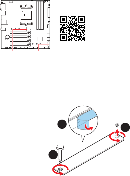
Important
If you are installing the screw-type CPU heatsink, please follow the figure below to
remove the retention module first and then install the heatsink.

5
Quick Start
Installing DDR4 memory
http://youtu.be/T03aDrJPyQs
DIMMA2 DIMMA2
DIMMB2
DIMMA1
DIMMA2
DIMMB1
DIMMB2

6
Quick Start
HDD LED
RESET SW
Connecting the Front Panel Header
http://youtu.be/DPELIdVNZUI
JFP1
HDD LED
HDD LED -
HDD LED +
POWER LED -
POWER LED +
POWER LED
1
2 10
9
+
+
+-
--
-
+
Power LED
HDD LED Reset Switch
Reserved
Power Switch
JFP1
1 HDD LED + 2 Power LED +
3 HDD LED - 4 Power LED -
5 Reset Switch 6 Power Switch
7 Reset Switch 8 Power Switch
9 Reserved 10 No Pin
RESET SW
POWER SW
POWER LED+
POWER LED-
HDD LED

7
Quick Start
BAT1
Installing the Motherboard
2
Torque:
3 kgf·cm*
*3 kgf·cm
= 0.3 N·m
= 2.6 lbf·in
https://youtu.be/wWI6Qt51Wnc
2
1

8
Quick Start
Connecting the Power Connectors
http://youtu.be/gkDYyR_83I4
ATX_PWR1
CPU_PWR1
CPU_PWR2

9
Quick Start
Installing SATA Drives
http://youtu.be/RZsMpqxythc
1
2
3
4
5

10
Quick Start
1
Installing a Graphics Card
http://youtu.be/mG0GZpr9w_A
2
3
4
5
6

11
Quick Start
Connecting Peripheral Devices
Processor with integrated graphics

12
Quick Start
Power On
4
3
1
2
13
Contents
Contents
Quick Start ............................................................................................................. 1
Preparing Tools and Components.......................................................................... 1
Safety Information .................................................................................................. 2
Installing a Processor ............................................................................................ 3
Installing DDR4 memory ........................................................................................ 5
Connecting the Front Panel Header ...................................................................... 6
Installing the Motherboard ..................................................................................... 7
Connecting the Power Connectors ........................................................................ 8
Installing SATA Drives ............................................................................................ 9
Installing a Graphics Card .................................................................................... 10
Connecting Peripheral Devices ............................................................................ 11
Power On .............................................................................................................. 12
Specifications ....................................................................................................... 15
Package contents ................................................................................................ 20
Block Diagram .................................................................................................... 21
Rear I/O Panel ..................................................................................................... 22
LAN Port LED Status Table .................................................................................. 22
Realtek Audio Console ......................................................................................... 22
Overview of Components .................................................................................... 25
Processor Socket ................................................................................................. 27
DIMM Slots ............................................................................................................ 28
PCI_E1~4: PCIe Expansion Slots .......................................................................... 29
SATA1~8: SATA 6Gb/s Connectors ....................................................................... 29
M2_1~2: M.2 Slots (Key M) ................................................................................... 30
JFP1, JFP2: Front Panel Connectors ................................................................... 32
JAUD1: Front Audio Connector ............................................................................ 32
CPU_PWR1, ATX_PWR1: Power Connectors ....................................................... 33
JUSB1: USB 3.2 Gen 1 5Gbps Type-C Connector ................................................. 34
JUSB2: USB 3.2 Gen 1 5Gbps Connector ............................................................. 34
JUSB3~4: USB 2.0 Connectors ............................................................................. 35
JTPM1: TPM Module Connector ........................................................................... 35
CPU_FAN1, PUMP_FAN1, SYS_FAN1~3: Fan Connectors .................................. 36
JCI1: Chassis Intrusion Connector ....................................................................... 37
JBAT1: Clear CMOS (Reset BIOS) Jumper ........................................................... 38
JRGB1: RGB LED connector ................................................................................. 39
JRAINBOW1: Addressable RGB LED connector .................................................. 40
14
Contents
EZ Debug LED ....................................................................................................... 41
LED_SW1: EZ LED Control ................................................................................... 41
Installing OS, Drivers & MSI Center .................................................................... 42
Installing Windows® 10 ......................................................................................... 42
MSI Center ............................................................................................................ 42
Installing Drivers with MSI Driver Utility Installer ............................................... 43
UEFI BIOS ............................................................................................................. 45
BIOS Setup ............................................................................................................ 46
Entering BIOS Setup ............................................................................................. 46
Resetting BIOS ...................................................................................................... 47
Updating BIOS ....................................................................................................... 47
EZ Mode ................................................................................................................ 49
Advanced Mode .................................................................................................... 52
SETTINGS Menu ................................................................................................... 53
OC Menu................................................................................................................ 55
M-FLASH Menu .................................................................................................... 58
OC PROFILE Menu ................................................................................................ 59
HARDWARE MONITOR Menu ............................................................................... 60
AMD RAID Configuration ..................................................................................... 62
Enabling RAIDXpert2 Configuration Utility .......................................................... 62
Initializing Disks ................................................................................................... 63
Creating Arrays..................................................................................................... 64
Deleting Arrays ..................................................................................................... 65
Installing RAID Driver ........................................................................................... 66
Troubleshooting ................................................................................................. 67

15
Specifications
Specifications
CPU
Supports AM4 socket 3rd Gen AMD Ryzen™ processors, and
future AMD Ryzen™ processors with BIOS update
Chipset AMD B550 Chipset
Memory
∙ 4x DDR4 memory slots, support up to 128GB*
▪ Supports DDR4 1866/ 2133/ 2400/ 2667/ 2800/ 2933/
3000/ 3066/ 3200 MHz by JEDEC
▪ Supports DDR4 2667/ 2800 /2933 /3000 /3066 /3200
/3466 /3600/ 3733 /3866 /4000 /4133 /4266 /4400+ MHz by
A-XMP OC MODE
▫ 1DPC 1R max speed 4400 MHz
▫ 1DPC 2R max speed 3733 MHz
▫ 2DPC 1R max speed 3866 MHz
▫ 2DPC 2R max speed 3466 MHz
∙ Dual channel memory architecture
∙ Supports non-ECC UDIMM memory
∙ Supports ECC UDIMM memory
∙ Supports un-buffered memory
* Please refer www.msi.com for more information on compatible memory.
Expansion Slot
∙ 1x PCIe 3.0/ 4.0 x16 slot (PCI_E1)*
∙ 3x PCIe 3.0 x16 slots, support PCIe x1 speed
* The supported specification depends on installed processor.
Onboard Graphics
∙ 1x VGA port, supports resolution of 2048x1536 @50Hz,
2048x1280 @60Hz, 1920x1200 @60Hz*
∙ 1x DisplayPort, supports a maximum resolution of
4096x2160 @60Hz*
∙ 1x HDMI 2.1 port, supports a maximum resolution of
4096x2160 @60Hz*
/
**
∙ Maximum shared memory of 16 GB
* Available for the processor with integrated graphics.
** Graphics specifications may vary depending on the CPU installed.
Continued on next page

16
Specifications
Continued from previous page
Storage
ASMedia AM1064 Chipset
∙ 4x SATA 6Gb/s ports
AMD B550 Chipset
∙ 4x SATA 6Gb/s ports
∙ 2x M.2 slots (Key M)
▪ M2_1 slot (from AMD processor)
▫ Supports PCIe 4.0/ 3.0 x4 *
▫ Supports SATA 6Gb/s
▫ Supports 2242/ 2260/ 2280 storage devices
▪ M2_2 slot (from AMD B550 chipset)
▫ Supports PCIe 3.0x4
▫ Supports 2242/ 2260/ 2280 storage devices
* The supported specification depends on installed processor.
RAID
∙ Supports RAID 0, RAID 1 and RAID 10 for SATA storage
devices
∙ Supports RAID 0 and RAID 1 for M.2 NVMe storage devices
USB
AMD B550 Chipset
▪ 3x USB 3.2 Gen 1 5Gbps ports (1 Type-C internal
connector, and 2 ports are available through the internal
USB 3.2 Gen 1 5Gbps connector)
▪ 6x USB 2.0 ports (2 Type-A ports on the back panel, 4
ports through the internal USB 2.0 connectors)
AMD Processor
▪ 2x USB 3.2 Gen 1 5Gbps Type-A ports on the back
panel
▪ 2x USB 3.2 Gen 2 10Gbps Type-A ports on the back
panel
Audio
Realtek® ALC892/ ALC897 Codec
▪ 7.1-Channel High Definition Audio
LAN
∙ 1x Realtek® RTL8111GN/ RTL8111HN 1Gbps LAN
controller
Continued on next page

17
Specifications
Continued from previous page
Wireless LAN &
Bluetooth®
AMD Wi-Fi 6E
∙ The Wireless module is pre-installed in the M.2 (Key-E)
slot
∙ Supports MU-MIMO TX/RX
∙ Supports 20MHz, 40MHz, 80MHz,160MHz bandwidth in
2.4GHz/ 5GHz or 6GHz* bands
∙ Supports 802.11 a/ b/ g/ n/ ac/ ax
∙ Supports Bluetooth® 5.2**
* Wi-Fi 6E 6GHz may depend on every country’s regulations and will be ready in
Windows 10 build 21H1 and Windows 11.
** Bluetooth 5.2 will be ready in Windows 10 build 21H1 and Windows 11.
Internal Connectors
∙ 1x 24-pin ATX main power connector
∙ 1x 8-pin ATX 12V power connector
∙ 8x SATA 6Gb/s connectors
∙ 2x M.2 slots (M-Key)
∙ 1x USB 3.2 Gen 1 5Gbps Type-C port
∙ 1x USB 3.2 Gen 1 5Gbps connector (supports additional 2
USB 3.2 Gen 1 5Gbps ports)
∙ 2x USB 2.0 connectors (supports additional 4 USB 2.0
ports)
∙ 1x 4-pin CPU fan connector
∙ 1x 4-pin water-pump fan connector
∙ 3x 4-pin system fan connectors
∙ 1x Front panel audio connector
∙ 2x System panel connectors
∙ 1x Chassis Intrusion connector
∙ 1x 4-pin RGB LED connector
∙ 1x 3-pin RAINBOW LED connector
∙ 1xTPM module connector
∙ 1x Clear CMOS jumper
LED Features
∙ 1x EZ LED Control switch
∙ 4x EZ Debug LED
Continued on next page

18
Specifications
Continued from previous page
Back Panel
Connectors
∙ 1x Flash BIOS Button
∙ 1x VGA port
∙ 1x Display port
∙ 1x HDMI port
∙ 2x USB 3.2 Gen 2 10Gbps Type-A ports
∙ 1x PS/2 keyboard/ mouse combo port
∙ 2x USB 2.0 Type-A ports
∙ 1x LAN (RJ45) port
∙ 2x USB 3.2 Gen 1 5Gbps Type-A ports
∙ 2x Wi-Fi Antenna connectors
∙ 3x Audio jacks
I/O Controller NUVOTON NCT6687D-R Controller Chip
Hardware Monitor
∙ CPU/ System/ Chipset temperature detection
∙ CPU/ System/ Pump fan speed detection
∙ CPU/ System/ Pump fan speed control
Form Factor
∙ Micro-ATX Form Factor
∙ 9.6 in. x 9.6 in. (24.4 cm x 24.4 cm)
BIOS Features
∙ 1x 256 Mb flash
∙ UEFI AMI BIOS
∙ ACPI 6.0, SMBIOS 2.8
∙ Multi-language
Software
∙ Drivers
∙ MSI Center
∙ CPU-Z MSI GAMING
∙ Google Chrome™, Google Toolbar, Google Drive
∙ Norton™ Internet Security Solution
Continued on next page

19
Specifications
Continued from previous page
MSI Center
Features
∙ Mystic Light
∙ Frozr AI Cooling
∙ User Scenario
∙ True Color
∙ Live Update
∙ Hardware Monitor
∙ Super Charger
∙ Speed Up
∙ Smart Image Finder
∙ MSI Companion
Special Features
∙ Audio
▪ Audio Boost
∙ Network
▪ Intel WiFi
∙ Cooling
▪ Pump Fan
▪ Smart Fan Control
∙ LED
▪ Mystic Light Extension (RAINBOW/RGB)
▪ EZ LED Control
▪ EZ DEBUG LED
∙ Performance
▪ DDR4 Boost
▪ Core Boost
▪ Creator Genie
▪ Front USB Type-C
∙ Protection
▪ PCI-E Steel Armor
∙ Experience
▪ MSI Center
▪ Click BIOS 5
▪ Flash BIOS Button

20
Package contents
Package contents
Please check the contents of your motherboard package. It should contain:
Motherboard PRO B550M-VC WIFI
Cable
SATA 6G cables
(2 cables/pack)
1
Accessories
Wi-Fi antenna 1
M.2 screws (3 pcs./pack) 1
I/O shield 1
Documentation Quick installation guide 1
⚠
Important
If any of the above items are damaged or missing, please contact your retailer.

21
Block Diagram
Block Diagram
2 Channel DDR4 Memory
PCIE
PCI Express Bus
Chipset
Processor
NUVOTON
6687
Realtek
ALC892/
3x USB 3.2 Gen1
6x USB 2.0
Rear Audio Jacks
Front Audio Jacks
1x M.2
1x Intel Wi-Fi
4x SATA 6Gb/s
1x M.2
2x USB 3.2 Gen1
1x Realtek 1Gbps LAN
Asmedia
AM1064
3x PCIe x16 slots
ALC897
4x SATA 6Gb/s
+2x USB 3.2 Gen2

22
Rear I/O Panel
USB 3.2 Gen 2
(10Gbps) Type-A
USB 3.2 Gen 1
(5Gbps) Type-A
Flash BIOS
Port
Rear I/O Panel
PS/2 Combo
1 Gbps LAN
DisplayPort
VGA
USB 2.0
Type-A
Wi-Fi Antenna
connectors
∙ Flash BIOS Port/ Button - Please refer to page 46 for Updating BIOS with Flash
BIOS Button.
Flash BIOS Button
Link/ Activity LED
Status Description
Off No link
Yellow Linked
Blinking Data activity
Speed LED
Status Description
Off 10 Mbps connection
Green 100 Mbps connection
Orange 1 Gbps connection
LAN Port LED Status Table
Realtek Audio Console
After Realtek Audio Console is installed. You can use it to change sound settings to get
better sound experience.
Jack Status
Connector Settings
Device
Selection
Main Volume
Application Enhancement
Line-In
Mic-In
Line-Out

23
Rear I/O Panel
∙ Device Selection - allows you to select a audio output source to change the related
options. The check sign indicates the devices as default.
∙ Application Enhancement - the array of options will provide you a complete
guidance of anticipated sound effect for both output and input device.
∙ Main Volume - controls the volume or balance the right/left side of the speakers
that you plugged in front or rear panel by adjust the bar.
∙ Jack Status - depicts all render and capture devices currently connected with your
computer.
∙ Connector Settings - configures the connection settings.
Audio 7.1-channel Configuration
To configure 7.1-channel audio, you have to connect front audio I/O module to JAUD1
connector and follow the below steps.
1. Click on the Realtek Audio Console > Device advanced settings to open the dialog
below.
2. Select Mute the rear output device, when a front headphone plugged in.
3. Plug your speakers to audio jacks on rear and front I/O panel. When you plug a
device into an audio jack, a dialogue window will pop up asking you which device is
current connected.
⚠
Important
The pictures above for reference only and may vary from the product you purchased.

24
Rear I/O Panel
Installing antennas
1. Screw the antennas tight to the antenna connectors as shown below.
2. Orient the antennas.
1
2

25
Overview of Components
BAT1
Overview of Components
JUSB3
LED_SW1
JRGB1
M2_1
JUSB1
JTPM1
JUSB2
JRAINBOW1
M2_2
CPU_FAN1
SYS_FAN2
SYS_FAN1
PCI_E1
PCI_E3
PCI_E2
JBAT1
PCI_E4
Processor Socket
CPU_PWR1
PUMP_FAN1
JAUD1
JUSB4
JCI1
JFP1
SATA5
SATA6
SATA7
SATA8
SYS_FAN3
JFP2
ATX_PWR1
DIMMB1
DIMMB2
DIMMA1
DIMMA2

26
Overview of Components
Component Contents
Port Name Port Type Page
CPU_FAN1, PUMP_FAN1,
SYS_FAN1~3
Fan Connectors 36
CPU_PWR1, ATX_PWR1 Power Connectors 33
DIMMA1, DIMMA2, DIMMB1,
DIMMB2
DIMM Slots 28
JAUD1 Front Audio Connector 32
JBAT1 Clear CMOS Jumper 38
JCI1 Chassis Intrusion Connector 37
JFP1, JFP2 Front Panel Connectors 32
JRAINBOW1 Addressable RGB LED connector 40
JRGB1 RGB LED connector 39
JTPM1 TPM Module Connector 35
JUSB1 USB 3.2 Gen 1 Type-C Connector 34
JUSB2 USB 3.2 Gen 1 Connector 34
JUSB3~4 USB 2.0 Connectors 35
LED_SW1 EZ LED Control 41
M2_1~2 M.2 Slots (Key M) 30
PCI_E1~4 PCIe Expansion Slots 29
Processor Socket Socket AM4 27
SATA1~8 SATA 6Gb/s Connectors 29

27
Overview of Components
Processor Socket
Introduction to the AM4 CPU
The surface of the AM4 CPU has a
yellow triangle to assist in correctly
lining up the CPU for motherboard
placement. The yellow triangle is
the Pin 1 indicator.
53.8 mm
Distance from the center of the
CPU to the nearest DIMM slot.
⚠
Important
∙
When changing the processor, the system configuration could be cleared and reset
BIOS to default values, due to the AM4 processor’s architecture.
∙
Always unplug the power cord from the power outlet before installing or removing
the CPU.
∙
When installing a CPU, always remember to install a CPU heatsink. A CPU heatsink
is necessary to prevent overheating and maintain system stability.
∙
Confirm that the CPU heatsink has formed a tight seal with the CPU before booting
your system.
∙
Overheating can seriously damage the CPU and motherboard. Always make sure
the cooling fans work properly to protect the CPU from overheating. Be sure to apply
an even layer of thermal paste (or thermal tape) between the CPU and the heatsink to
enhance heat dissipation.
∙
If you purchased a separate CPU and heatsink/ cooler, Please refer to the
documentation in the heatsink/ cooler package for more details about installation.
∙
This motherboard is designed to support overclocking. Before attempting to
overclock, please make sure that all other system components can tolerate
overclocking. Any attempt to operate beyond product specifications is not
recommended. MSI
®
does not guarantee the damages or risks caused by inadequate
operation beyond product specifications.

28
Overview of Components
DIMM Slots
DIMMA1 DIMMB1
Channel A Channel B
DIMMA2 DIMMB2
Memory module installation recommendation
⚠
Important
∙
Always insert memory modules in the DIMMA2 slot first.
∙
Due to chipset resource usage, the available capacity of memory will be a little less
than the amount of installed.
∙
Based on CPU specification, the Memory DIMM voltage below 1.35V is suggested to
protect the CPU.
∙
To ensure system stability for Dual channel mode, memory modules must be of the
same type, number and density.
∙
Some memory modules may operate at a lower frequency than the marked value
when overclocking due to the memory frequency operates dependent on its Serial
Presence Detect (SPD). Go to BIOS and find the DRAM Frequency to set the memory
frequency if you want to operate the memory at the marked or at a higher frequency.
∙
It is recommended to use a more efficient memory cooling system for full DIMMs
installation or overclocking.
∙
The stability and compatibility of installed memory module depend on installed CPU
and devices when overclocking.
∙
Please refer www.msi.com for more information on compatible memory.
DIMMB2 DIMMB2
DIMMB1
DIMMA2
DIMMA2
DIMMA2
DIMMA1

29
Overview of Components
PCI_E1~4: PCIe Expansion Slots
⚠
Important
∙
If you install a large and heavy graphics card, you need to use a tool such as MSI
Gaming Series Graphics Card Bolster to support its weight to prevent deformation of
the slot.
∙
When adding or removing expansion cards, always turn off the power supply and
unplug the power supply power cable from the power outlet. Read the expansion
card’s documentation to check for any necessary additional hardware or software
changes.
BAT1
PCI_E1 PCIe 3.0/ 4.0 x16 (CPU)
PCI_E3 PCIe 3.0 x1 (PCH)
PCI_E4 PCIe 3.0 x1 (PCH)
PCI_E2 PCIe 3.0 x1 (PCH)
SATA1~8: SATA 6Gb/s Connectors
These connectors are SATA 6Gb/s interface ports. Each connector can connect to one
SATA device.
⚠
Important
∙
Please do not fold the SATA cable at a 90-degree angle. Data loss may result during
transmission otherwise.
∙
SATA cables have identical plugs on either sides of the cable. However, it is
recommended that the flat connector be connected to the motherboard for space
saving purposes.
SATA1
SATA3
SATA5
SATA6
SATA7
SATA8
SATA2
SATA4
30
Overview of Components
M2_1~2: M.2 Slots (Key M)
M2_1 M2_2
⚽
Video Demonstration
Watch the video to learn how to Install
M.2 module.
http://youtu.be/JCTFABytrYA
M2_1 slot installation
1. Loosen the screws of M.2 SHIELD FROZR heatsink.
2. Remove the M.2 SHIELD FROZR and remove the protective films from the thermal
pads.
1
1
2

31
Overview of Components
30º30º
M.2 standoff
heatsink standoff
3
5
4
M.2 screw
6
6
M2_2 slot installation
1. Move the position of the standoffs according to your M.2 SSDs length if need.
2. Insert your M.2 SSD into the M.2 slot at a 30-degree angle.
3. Secure the M.2 SSD in place with the supplied M.2 screw.
3. Move and fasten the M.2 standoff to the appropriate position for your M.2 SSD,
or remove the M.2 standoff if your M.2 SSD length is same as the length of M.2
heatsink to avoid damage to the M.2 SSD.
4. Insert your M.2 SSD into the M.2 slot at a 30-degree angle.
5. Secure the M.2 SSD in place with the M.2 screw, or skip this step if you remove the
M.2 standoff in step 3.
6. Put the M.2 SHIELD FROZR heatsink back in place and secure it.

32
Overview of Components
JAUD1: Front Audio Connector
This connector allows you to connect audio jacks on the front panel.
1
2 10
9
1 MIC L 2 Ground
3 MIC R 4 NC
5 Head Phone R 6 MIC Detection
7 SENSE_SEND 8 No Pin
9 Head Phone L 10 Head Phone Detection
JFP1, JFP2: Front Panel Connectors
These connectors connect to the switches and LEDs on the front panel.
JFP2
1
+
+
-
-
Speaker
Buzzer
1 Speaker - 2 Buzzer +
3 Buzzer - 4 Speaker +
1
2 10
9
+
+
+-
--
-
+
Power LED
HDD LED Reset Switch
Reserved
Power Switch
JFP1
1 HDD LED + 2 Power LED +
3 HDD LED - 4 Power LED -
5 Reset Switch 6 Power Switch
7 Reset Switch 8 Power Switch
9 Reserved 10 No Pin

33
Overview of Components
24
131
12
ATX_PWR1
1 +3.3V 13 +3.3V
2 +3.3V 14 -12V
3 Ground 15 Ground
4 +5V 16 PS-ON#
5 Ground 17 Ground
6 +5V 18 Ground
7 Ground 19 Ground
8 PWR OK 20 Res
9 5VSB 21 +5V
10 +12V 22 +5V
11 +12V 23 +5V
12 +3.3V 24 Ground
5
4 1
8
CPU_PWR1
1 Ground 5 +12V
2 Ground 6 +12V
3 Ground 7 +12V
4 Ground 8 +12V
⚠
Important
Make sure that all the power cables are securely connected to a proper ATX power
supply to ensure stable operation of the motherboard.
CPU_PWR1, ATX_PWR1: Power Connectors
These connectors allow you to connect an ATX power supply.

34
Overview of Components
JUSB1: USB 3.2 Gen 1 5Gbps Type-C Connector
This connector allows you to connect USB 3.2 Gen 1 5Gbps Type-C connector on the
front panel. The connector possesses a foolproof design. When you connect the cable,
be sure to connect it with the corresponding orientation.
JUSB2: USB 3.2 Gen 1 5Gbps Connector
This connector allows you to connect USB 3.2 Gen 1 5Gbps ports on the front panel.
⚠
Important
Note that the Power and Ground pins must be connected correctly to avoid possible
damage.
1 10
11
20
1 Power 11 USB2.0+
2 USB3_RX_DN 12 USB2.0-
3 USB3_RX_DP 13 Ground
4 Ground 14 USB3_TX_C_DP
5 USB3_TX_C_DN 15 USB3_TX_C_DN
6 USB3_TX_C_DP 16 Ground
7 Ground 17 USB3_RX_DP
8 USB2.0- 18 USB3_RX_DN
9 USB2.0+ 19 Power
10 Ground 20 No Pin
JUSB1
USB Type-C Cable
USB Type-C port on
the front panel

35
Overview of Components
JUSB3~4: USB 2.0 Connectors
These connectors allow you to connect USB 2.0 ports on the front panel.
1
2 10
9
1 VCC 2 VCC
3 USB0- 4 USB1-
5 USB0+ 6 USB1+
7 Ground 8 Ground
9 No Pin 10 NC
⚠
Important
∙
Note that the VCC and Ground pins must be connected correctly to avoid possible
damage.
∙
In order to recharge your iPad,iPhone and iPod through USB ports, please install
MSI Center utility.
1
212
11
1 SPI Power 2 SPI Chip Select
3
Master In Slave Out (SPI Data)
4
Master Out Slave In (SPI Data)
5 Reserved 6 SPI Clock
7 Ground 8 SPI Reset
9 Reserved 10 No Pin
11 Reserved 12 Interrupt Request
JTPM1: TPM Module Connector
This connector is for TPM (Trusted Platform Module). Please refer to the TPM security
platform manual for more details and usages.

36
Overview of Components
CPU_FAN1, PUMP_FAN1, SYS_FAN1~3: Fan Connectors
Fan connectors can be classified as PWM (Pulse Width Modulation) Mode or DC Mode.
PWM Mode fan connectors provide constant 12V output and adjust fan speed with
speed control signal. DC Mode fan connectors control fan speed by changing voltage.
The auto mode fan connectors can automatically detect PWM and DC mode. However,
you can follow the instruction below to adjust the fan connector to PWM or DC Mode
manually.
Switching fan mode and adjusting fan speed
You can switch between PWM mode and DC mode and adjust fan speed in BIOS >
HARDWARE MONITOR.
Select PWM mode or DC mode
⚠
Important
Make sure fans are working properly after switching the PWM/ DC mode.
There are gradient points of the fan speed that allow you to adjust
fan speed in relation to CPU temperature.
Pin definition of fan connectors
CPU_FAN1
SYS_FAN3
PUMP_FAN1
SYS_FAN1
SYS_FAN2
Connector
Default fan
mode
Max.
current
Max.
power
CPU_FAN1 Auto mode 2A 24W
PUMP_FAN1 PWM mode 3A 36W
SYS_FAN1~3 DC mode 1A 12W
1
PWM Mode pin definition
1 Ground 2 +12V
3 Sense 4 Speed Control Signal
1
DC Mode pin definition
1 Ground 2 Voltage Control
3 Sense 4 NC

37
Overview of Components
JCI1: Chassis Intrusion Connector
This connector allows you to connect the chassis intrusion switch cable.
Normal
(default)
Trigger the chassis
intrusion event
Using chassis intrusion detector
1. Connect the JCI1 connector to the chassis intrusion switch/ sensor on the chassis.
2. Close the chassis cover.
3. Go to BIOS > SETTINGS > Security > Chassis Intrusion Configuration.
4. Set Chassis Intrusion to Enabled.
5. Press F10 to save and exit and then press the Enter key to select Yes.
6. Once the chassis cover is opened again, a warning message will be displayed on
screen when the computer is turned on.
Resetting the chassis intrusion warning
1. Go to BIOS > SETTINGS > Security > Chassis Intrusion Configuration.
2. Set Chassis Intrusion to Reset.
3. Press F10 to save and exit and then press the Enter key to select Yes.

38
Overview of Components
JBAT1: Clear CMOS (Reset BIOS) Jumper
There is CMOS memory onboard that is external powered from a battery located on
the motherboard to save system configuration data. If you want to clear the system
configuration, set the jumpers to clear the CMOS memory.
Keep Data
(default)
Clear CMOS/
Reset BIOS
Resetting BIOS to default values
1. Power off the computer and unplug the power cord.
2. Use a jumper cap to short JBAT1 for about 5-10 seconds.
3. Remove the jumper cap from JBAT1.
4. Plug the power cord and Power on the computer.

39
Overview of Components
⚠
Important
∙
The JRGB connector supports up to 2 meters continuous 5050 RGB LED strips
(12V/G/R/B) with the maximum power rating of 3A (12V).
∙
Always turn off the power supply and unplug the power cord from the power outlet
before installing or removing the RGB LED strip.
∙
Please use MSI’s software to control the extended LED strip.
JRGB1: RGB LED connector
The JRGB connector allows you to connect the 5050 RGB LED strips 12V.
1
G
R
B
JRGB
connector
RGB extension
cable
5050 RGB LED strips 12V
1
1 +12V 2 G
3 R 4 B
RGB LED Strip Connection
1
1
G
R
B
JRGB connector
System Fan connector
RGB LED Fan Connection
RGB LED Fan

40
Overview of Components
1
1
1
D
+5V
⚠
CAUTION
Do not connect the wrong type of LED strips. The JRGB connector and the JRAINBOW
connector provide different voltages, and connecting the 5V LED strip to the JRGB
connector will result in damage to the LED strip.
⚠
Important
∙
The JRAINBOW connector supports up to 75 LEDs WS2812B Individually
Addressable RGB LED strips (5V/Data/Ground) with the maximum power rating of 3A
(5V). In the case of 20% brightness, the connector supports up to 200 LEDs.
∙
Always turn off the power supply and unplug the power cord from the power outlet
before installing or removing the RGB LED strip.
∙
Please use MSI’s software to control the extended LED strip.
JRAINBOW1: Addressable RGB LED connector
The JRAINBOW connector allows you to connect the WS2812B Individually
Addressable RGB LED strips 5V.
JRAINBOW
connector
JRAINBOW connector
System Fan connector
Rainbow RGB LED
extension cable
WS2812B Individually
Addressable RGB LED strips 5V
1
1 +5V 2 Data
3 No Pin 4 Ground
Addressable RGB LED Strip Connection
Addressable RGB LED Fan Connection
Addressable RGB LED Fan

41
Overview of Components
EZ Debug LED
These LEDs indicate the debug status of the motherboard.
CPU - indicates CPU is not detected or fail.
DRAM - indicates DRAM is not detected or fail.
VGA - indicates GPU/ PCIE/ M.2 device is not detected
or fail.
BOOT - indicates the booting device is not detected
or fail.
LED_SW1: EZ LED Control
This switch is used to switch on/ off all the LEDs of motherboard.
LED_OFF
LED_ON
(Default)

42
Installing OS, Drivers & MSI Center
Installing OS, Drivers & MSI Center
Please download and update the latest utilities and drivers at www.msi.com
Installing Windows® 10
1. Power on the computer.
2. Insert the Windows® 10 installation disc/USB into your computer.
3. Press the Restart button on the computer case.
4. Press F11 key during the computer POST (Power-On Self Test) to get into Boot
Menu.
5. Select the Windows® 10 installation disc/USB from the Boot Menu.
6. Press any key when screen shows Press any key to boot from CD or DVD...
message.
7. Follow the instructions on the screen to install Windows® 10.
MSI Center
MSI Center is an application that helps you easily optimize game settings and smoothly
use content creation softwares. It also allows you to control and synchronize LED
light effects on PCs and other MSI products. With MSI Center, you can customize ideal
modes, monitor system performance, and adjust fan speed.
MSI Center User Guide
If you would like to know more information about MSI Center, please
refer to
http://download.msi.com/manual/mb/MSICENTER.pdf
or scan the QR code to access.
⚠
Important
Functions may vary depending on the product you have.

43
Installing OS, Drivers & MSI Center
Installing Drivers with MSI Driver Utility Installer
⚠
Important
∙
Some new network chips have not been natively supported by Windows 10/ Windows
11. It is recommended that the LAN driver be installed before installing drivers with
MSI Driver Utility Installer. Please refer to www.msi.com to install the LAN driver for
your motherboard.
∙
The MSI Driver Utility Installer will only pop up once. If you cancel or close it during
the process, please refer to the Live Update chapter of the MSI Center manual to
install the drivers. You can also go to www.msi.com to search your motherboard and
download the drivers.
∙
MSI Driver Utility Installer needs to be installed over the internet.
1. Start up your computer in Windows 10/ Windows 11.
2. Select Start > Settings > Windows Update, and then select Check for updates.
3. MSI Driver Utility Installer will pop up automatically.
4. Select the I have read and agree to the MSI Terms of Use check box, and then click
Next.

44
Installing OS, Drivers & MSI Center
5. Check the Select All checkbox in the lower-left corner and click Install to install
MSI Center and drivers. The installation progress will be shown at the bottom.
6. Once the progress has completed, click Finish.

45
UEFI BIOS
UEFI BIOS
MSI UEFI BIOS is compatible with UEFI (Unified Extensible Firmware Interface)
architecture. UEFI has many new functions and advantages that traditional BIOS
cannot achieve, and it will completely replace BIOS in the future. The MSI UEFI
BIOS uses UEFI as the default boot mode to take full advantage of the new chipset’s
capabilities. However, it still has a CSM (Compatibility Support Module) mode to be
compatible with older devices. That allows you to replace legacy devices with UEFI
compatible devices during the transition.
⚠
Important
The term BIOS in this user guide refers to UEFI BIOS unless otherwise noted.
UEFI advantages
∙ Fast booting - UEFI can directly boot the operating system and save the BIOS self-
test process. And also eliminates the time to switch to CSM mode during POST.
∙ Supports for hard drive partitions larger than 2 TB.
∙ Supports more than 4 primary partitions with a GUID Partition Table (GPT).
∙ Supports unlimited number of partitions.
∙ Supports full capabilities of new devices - new devices may not provide backward
compatibility.
∙ Supports secure startup - UEFI can check the validity of the operating system to
ensure that no malware tampers with the startup process.
Incompatible UEFI cases
∙ 32-bit Windows operating system - this motherboard supports only Windows 10
64-bit operating system.
∙ Older graphics card - the system will detect your graphics card. When display a
warning message There is no GOP (Graphics Output protocol) support detected in
this graphics card.
⚠
Important
We recommend that you to use a GOP/ UEFI compatible graphics card.
How to check the BIOS mode?
After entering the BIOS, find the BIOS Mode at the top of the screen.
CPU Temperature:
Motherboard Temperature:
VCore:
DDR Voltage:
BIOS Mode: UEFI/CSM
CPU Temperature:
Motherboard Temperature:
VCore:
DDR Voltage:
BIOS Mode: UEFI/CSM
UEFI boot mode CSM boot mode
46
UEFI BIOS
BIOS Setup
The default settings offer the optimal performance for system stability in normal
conditions. You should always keep the default settings to avoid possible system
damage or failure booting unless you are familiar with BIOS.
⚠
Important
∙
BIOS items are continuously update for better system performance. Therefore, the
description may be slightly different from the latest BIOS and should be for reference
only. You could also refer to the HELP information panel for BIOS item description.
∙
The pictures in this chapter are for reference only and may vary from the product
you purchased.
∙
The BIOS items will vary with the processor.
Entering BIOS Setup
Press Delete key, when the Press DEL key to enter Setup Menu, F11 to enter Boot
Menu message appears on the screen during the boot process.
Function key
F1: General Help list
F2: Add/ Remove a favorite item
F3: Enter Favorites menu
F4: Enter CPU Specifications menu
F5: Enter Memory-Z menu
F6: Load optimized defaults
F7: Switch between Advanced mode and EZ mode
F8: Load Overclocking Profile
F9: Save Overclocking Profile
F10: Save Change and Reset*
F12: Take a screenshot and save it to USB flash drive (FAT/ FAT32 format only).
Ctrl+F: Enter Search page
* When you press F10, a confirmation window appears and it provides the modification
information. Select between Yes or No to confirm your choice.

47
UEFI BIOS
Resetting BIOS
You might need to restore the default BIOS setting to solve certain problems. There
are several ways to reset BIOS:
∙ Go to BIOS and press F6 to load optimized defaults.
∙ Short the Clear CMOS jumper on the motherboard.
⚠
Important
Be sure the computer is off before clearing CMOS data. Please refer to the Clear
CMOS jumper section for resetting BIOS.
Updating BIOS
Updating BIOS with M-FLASH
Before updating:
Please download the latest BIOS file that matches your motherboard model from MSI
website. And then save the BIOS file into the USB flash drive.
Updating BIOS:
1. Insert the USB flash drive that contains the update file into the USB port.
2. Please refer the following methods to enter flash mode.
▪ Reboot and press Ctrl + F5 key during POST and click on Yes to reboot the
system.
Press <Ctrl+F5> to activate M-Flash for BIOS update.
▪ Reboot and press Del key during POST to enter BIOS. Click the M-FLASH button
and click on Yes to reboot the system.
3. Select a BIOS file to perform the BIOS update process.
4. When prompted click on Yes to start recovering BIOS.
5. After the flashing process is 100% completed, the system will reboot
automatically.
48
UEFI BIOS
Updating BIOS with Flash BIOS Button
1. Please download the latest BIOS file that matches your motherboard model from
the MSI® website.
2. Rename the BIOS file to MSI.ROM, and save it to the root of your USB flash drive.
3. Connect the power supply to CPU_PWR1 and ATX_PWR1. (No need to install CPU
and memory.)
4. Plug the USB flash drive that contains the MSI.ROM file into the Flash BIOS Port
on the rear I/O panel.
5. Press the Flash BIOS Button to flash BIOS, and the LED starts flashing.
6. The LED will be turned off when the process is completed.

49
UEFI BIOS
EZ Mode
At EZ mode, it provides the basic system information and allows you to configure the
basic setting. To configure the advanced BIOS settings, please enter the Advanced
Mode by pressing the Setup Mode switch or F7 function key.
A-XMP Profile
Component
Information
System
information
Boot device
priority bar
Function
buttons
Language
CREATOR
GENIE
Search
Screenshot
Setup Mode switch
M-Flash
Hardware
Monitor
Favorites
∙ CREATOR GENIE - click on it to toggle the CREATOR GENIE for performance
optimization. This function is only available when both of the motherboard and CPU
are supporting this function.
⚠
Important
Please don’t make any changes in OC menu and don’t load defaults to keep the
optimal performance and system stability after activating the CREATOR GENIE
function.
∙ A-XMP Profile - allows you to select the A-XMP profile for memory to overclock.
This function is only available when the system, memory and CPU are supporting this
function.
∙ Setup Mode switch - press this tab or the F7 key to switch between Advanced mode
and EZ mode.
∙ Screenshot - click on this tab or the F12 key to take a screenshot and save it to USB
flash drive (FAT/ FAT32 format only).
∙ Search - click on this tab or the Ctrl+F keys to enter the search page. It allows you
to search by BIOS item name. Move the mouse over a blank space and right click the
mouse to exit the search page.
⚠
Important
In search page, only the F6, F10 and F12 function keys are available.
∙ Language - allows you to select language of BIOS setup.

50
UEFI BIOS
∙ System information - shows the CPU/ DDR speed, CPU/ MB temperature, MB/ CPU
type, memory size, CPU/ DDR voltage, BIOS version and build date.
∙ Boot device priority bar - you can move the device icons to change the boot priority.
The boot priority from high to low is left to right.
∙ Component Information - click on the CPU, Memory, Storage, Fan Info and Help
buttons to show the information of connected component.
∙ Function buttons - enable or disable these functions by clicking on these buttons.
The function is enabled when the button shows ON .
⚠
Important
The function buttons will vary with the motherboard you purchased.
∙ M-Flash - click on this button to enter the M-Flash menu that provides the way to
update BIOS with a USB flash drive.
∙ Hardware Monitor - click on this button to enter the Hardware Monitor menu that
allows you to manually control the fan speed by percentage.
∙ Favorites - click on this button or press the F3 key to show the Favorites window.
It provides 5 menus for you to create personal BIOS menu where you can save and
access favorite/ frequently-used BIOS setting items.

51
UEFI BIOS
▪ To add a BIOS item to a favorite menu
1. Select a BIOS item not only on BIOS menu but also on search page.
2. Right-click or press F2 key.
3. Choose a favorite page and click on OK.
▪ To delete a BIOS item from favorite menu
1. Select a BIOS item on favorite menu.
2. Right-click or press F2 key.
3. Choose Delete and click on OK.

52
UEFI BIOS
Advanced Mode
Press Setup Mode switch or F7 function key can switch between EZ Mode and
Advanced Mode in BIOS setup.
BIOS menu
selection
Menu display
BIOS menu
selection
∙ BIOS menu selection - the following options are available:
▪ SETTINGS - allows you to specify the parameters for chipset and boot devices.
▪ OC - allows you to adjust the frequency and voltage. Increasing the frequency
may get better performance.
▪ M-FLASH - provides the way to update BIOS with a USB flash drive.
▪ OC PROFILE - allows you to manage overclocking profiles.
▪ HARDWARE MONITOR - allows you to set the speeds of fans and monitor
voltages of system.
▪ BOARD EXPLORER - provides the information of installed devices on this
motherboard.
∙ Menu display - provides BIOS setting items and information to be configured.
53
UEFI BIOS
SETTINGS Menu
This menu allows you to specify the parameters for system, chipset and boot devices.
▶ System Status sub-menu
The System Status sub-menu allows you to set the system clock and view system
information.
▶ System Date
Sets the system date. Use tab key to switch between date elements.
The format is <day> <month> <date> <year>.
<day> Day of the week, from Sun to Sat, determined by BIOS. Read-only.
<month> The month from Jan. through Dec.
<date> The date from 1 to 31 can be keyed by numeric function keys.
<year> The year can be adjusted by users.
▶ System Time
Sets the system time. Use tab key to switch between time elements.
The time format is <hour> <minute> <second>.
▶ SATA PortX/ M2_X
Shows the information of connected SATA/ M.2 device.
⚠
Important
If the connected SATA/ M.2 device is not displayed, turn off computer and re-check
SATA/ M.2 cable and power cable connections of the device and motherboard.
▶ System Information
Shows detailed system information, including CPU type, BIOS version, and Memory
(read only).
▶ DMI Information
Shows system information, desktop board information and chassis information.
▶ Advanced sub-menu
The Advanced sub-menu allows you to adjust and set the parameters and behaviors of
PCIe, ACPI, integrated peripherals, integrated graphics, USB, power management and
Windows .
▶ PCI Subsystem Settings
Sets PCI, PCI express interface protocol and latency timer. Press Enter to enter
the sub-menu.
▶ ACPI Settings
Sets ACPI parameters of onboard power LED behaviors.
▶ Integrated Peripherals sub-menu
Sets integrated peripherals’ parameters, such as LAN, Wi-Fi, HDD, SSD, USB and
audio.
54
UEFI BIOS
▶ Integrated Graphics Configuration sub-menu (optional)
Adjusts integrated graphics settings for optimum system. This sub-menu is only
available when using the CPU which integrate with IGP.
▶ USB Configuration sub-menu
Sets the onboard USB controller and device function. Press Enter to enter the
sub-menu.
▶ Power Management Setup sub-menu
Sets system Power Management of ErP and AC Power Loss behaviors. You can
optimize the system power consumption in this menu.
▶ Windows OS Configuration
boot and control key management to prevent the unauthorized accessing for
system.
▶ Wake Up Event Setup sub-menu
▶ Secure Erase+
Enables or disables Secure Erase+ function. Secure Erase+ is the best way to
after enabling Secure Erase+.
▶ Realtek PCIe GbE Family Controller (MAC sub-menu
controller parameter.
▶ Boot sub-menu
Use this menu to set the system boot states and the sequence of system boot devices.
▶ Security sub-menu
Use this menu to set the administrator password and the user password for system
security. This menu also allows you to set the TPM (Trusted Platform Module)
function.
⚠
Important
When selecting the Administrator / User Password items, a password box will appear
on the screen. Type the password then press Enter. The password typed now will
replace any previous set password from CMOS memory. You will be prompted to
confirm the password. You may also press Esc key to abort the selection.
To clear a set password, press Enter when you are prompted to enter a new
password. A message will confirm the password is being disabled. Once the password
is disabled, you can enter the setup and OS without authorization.
▶ Save & Exit
This menu allows you to load the BIOS default values or factory default settings into
the BIOS and exit the BIOS setup utility with or without changes.
55
UEFI BIOS
OC Menu
This menu allows you to configure the frequencies and voltages for overclocking.
Please note that, higher frequency and voltage may benefit overclocking capability but
cause system un-stability.
⚠
Important
∙
Overclocking your PC manually is only recommended for advanced users.
∙
Overclocking is not guaranteed, and if done improperly, it could void your warranty
or severely damage your hardware.
∙
If you are unfamiliar with overclocking, we advise you to use CREATOR GENIE
function for easy overclocking.
∙
The BIOS items in OC menu will vary with the processor.
▶ OC Explore Mode [Normal]
Enables or disables to show the normal or expert version of OC settings.
[Normal] Provides the regular OC settings in BIOS setup.
[Expert] Provides the advanced OC settings for OC expert to configure in BIOS
setup.
Note: We use * as the symbol for the OC settings of Expert mode.
▶ CPU Ratio [Auto]
Sets the CPU ratio that is used to determine CPU clock speed. This item can only be
changed if the processor supports this function.
▶ Advanced CPU Conguration
Press Enter to enter the sub-menu. User can set the parameters about CPU
power/ current. The system may become unstable or unbootable after changing the
parameters. If it occurs, please clear the CMOS data and restore the default settings.
▶ A-XMP [Disabled]
Please enable A-XMP or select a profile of memory module for overclocking the
memory. This item will be available when the installed processor, memory modules
and motherboard support this function.
▶ DRAM Frequency [Auto]
Sets the DRAM frequency. Please note the overclocking behavior is not guaranteed.
▶ Adjusted DRAM Frequency
Shows the adjusted DRAM frequency. Read-only.
56
UEFI BIOS
▶ FCLK Frequency [Auto]
Sets the FCLK frequency (Internal Data Fabric clock of DRAM). Please note the
overclocking behavior is not guaranteed.
▶ UCLK DIV1 Mode [Auto]
Sets UCLK (Internal memory controller clock) mode.
▶ Memory Try It ! [Disabled]
It can improve memory compatibility or performance by choosing optimized memory
preset. This item will be available when the installed processor supports this function.
▶ Memory Failure Retry [Enabled]
Enables or disables the system reboot function when the memory OC retry fails.
▶ Memory Failure Retry Count [2]
Sets the count for memory OC retry. When memory OC retry fails reach the count,
the memory will restore the last available settings. This item will display when the
Memory Failure Retry sets to Enabled.
▶ Advanced DRAM Conguration
Press Enter to enter the sub-menu. User can set the memory timing for each/ all
memory channel. The system may become unstable or unbootable after changing
memory timing. If it occurs, please clear the CMOS data and restore the default
settings. (Refer to the Clear CMOS jumper section to clear the CMOS data, and enter
the BIOS to load the default settings.)
▶ DigitALL Power sub-menu
Press Enter to enter the sub-menu. In the sub-menu, you can setup some protecting
conditions about voltage/ current/ temputure for CPU.
▶ CPU Voltages control [Auto]
These options allows you to set the voltages related to CPU. If set to Auto, BIOS will
set these voltages automatically or you can set it manually.
▶ DRAM Voltages control [Auto]
These options allows you to set the voltages related to memory. If set to Auto, BIOS
will set these voltages automatically or you can set it manually.
▶ CHIP Voltages control [Auto] (optional)
These options allows you to set the voltages related to chipset If set to Auto, BIOS will
set these voltages automatically or you can set it manually.
57
UEFI BIOS
▶ Memory Changed Detect [Enabled]*
Enables or disables the system to issue a warning message during boot when the
memory has been replaced.
[Enabled] The system will issue a warning message during boot and then you have
to load the default settings for new devices.
[Disabled] Disables this function and keeps the current BIOS settings.
▶ CPU Specications sub-menu
Press Enter to enter the sub-menu. This sub-menu displays the information of
installed CPU. You can also access this information menu at any time by pressing [F4].
Read only.
▶ MEMORY-Z sub-menu
Press Enter to enter the sub-menu. This sub-menu displays all the settings and
timings of installed memory. You can also access this information menu at any time by
pressing [F5].

58
UEFI BIOS
M-FLASH Menu
M-FLASH provides the way to update BIOS with a USB flash drive. Please download
the latest BIOS file that matches your motherboard model from MSI website, save the
BIOS file into your USB flash drive. And then follow the steps below to update BIOS.
1. Insert the USB flash drive that contains the update file into the computer.
2. Click on M-FLASH tab, a demand message will be prompted. Click on Yes to
reboot and enter the flash mode.
3. The system will enter the flash mode and a file selection menu will appear after
rebooting.
4. Select a BIOS file to perform the BIOS update process.
5. After the flashing process is 100% completed, the system will reboot
automatically.

59
UEFI BIOS
OC PROFILE Menu
▶ Overclocking Prole 1/ 2/ 3/ 4/ 5/ 6
Overclocking Profile 1/ 2/ 3/ 4/ 5/ 6 management. Press Enter to enter the sub-menu.
▶ Set Name for Overclocking Profile 1/ 2/ 3/ 4/ 5/ 6
▶ Save Overclocking Profile 1/ 2/ 3/ 4/ 5/ 6
▶ Load Overclocking Profile 1/ 2/ 3/ 4/ 5/ 6
▶ Clear Overclocking Profile 1/ 2/ 3/ 4/ 5/ 6
▶ OC Prole Load from ROM
Load OC profile from BIOS ROM.
▶ OC Prole Save to USB
Save OC profile to the USB flash drive. The USB flash drive should be FAT/ FAT32
format only.
▶ OC Prole Load from USB
Load OC profile from the USB flash drive. The USB flash drive should be FAT/ FAT32
format only.

60
UEFI BIOS
HARDWARE MONITOR Menu
This menu allows you to adjust the fan speed manually and monitor CPU/ system
voltage.
Fan operating
window
Smart Fan duty
information
Click to enable
the Smart Fan
Temperature
information
Setting Buttons
Select a fan to be configured
Select a temperature curve line (white)
to be showed in Fan operating window
Select a fan mode for target fan
Voltage
information
∙ Smart Fan - This setting enables/disables the Smart Fan function. Smart Fan is an
excellent feature which will adjust the CPU/system fan speed automatically depending
on the current CPU/system temperature, avoiding the overheating to damage your
system.
▶ Settings Buttons
▪ All Full Speed - configures all fans to run at full operating speed.
▪ All Set Default - configures all fans’ speeds return the BIOS default values.
▪ All Set Cancel - discards current changes and restores previous settings for all
fan .
⚠
Important
Make sure fans are working properly after adjusting the fan speed and switching the
fan mode.

61
UEFI BIOS
Adjusting fans
1. Selects a fan that you want to adjust and to display the fan duty curve line (yellow)
in fan operating windows.
2. Click and drag the duty points to adjust the fan speed.
Duty points
Select a fan to be adjusted
⚠
Important
The pictures in this section are for reference only and may vary from the motherboard
you purchased.

62
AMD RAID Configuration
AMD RAID Configuration
The following are the RAID levels supported by RAIDXpert2.
RAID 0 (Striping) breaks the data into blocks which are written to separate hard
drives. Spreading the hard drive I/O load across independent channels
greatly improves I/O performance.
RAID 1 (Mirroring) provides data redundancy by mirroring data between the hard
drives and provides enhanced read performance.
RAID 10 (Striped RAID1 Sets) uses four hard drives to create a combination of RAID 0
and 1 by forming a RAID 0 array from two RAID 1 arrays.
Volume (JBOD) provides the ability to link-together storage from one or several
disks, regardless of the size of the space on those disks. Useful in
scavenging space on disks unused by other disks in the array. Does not
provide performance benefits or data redundancy.
RAIDABLE (also known as RAID Ready) allows the user to add more storage space or
create a redundant array after a system is installed.
RAID level comparison
RAID 0 RAID 1 RAID 10
Minimum # drives 2 2 4
Data protection None Excellent Excellent
Read performance Excellent OK OK
Write performance Excellent Good Good
Capacity utilization 100% 50% 50%
⚠
Important
All the information/ volumes/ pictures listed in your system might differ from the
illustrations in this appendix.
Enabling RAIDXpert2 Configuration Utility
To enter the RAIDXpert2 Configuration Utility menu
1. Power on and press Delete key to enter BIOS Setup menu.
2. Press F7 to switch to Advanced mode from EZ mode.
3. Go to BIOS > SETTINGS > Advanced > Integrated Peripherals > SATA Mode and
change setting to RAID Mode.
4. Go to BIOS > SETTINGS > Advanced > Windows OS Configuration > BIOS UEFI/
CSM Mode and change setting to UEFI.
5. Press F10 to save configuration and exit, and then reboot and press Delete key to
enter BIOS Setup menu.
6. Go to BIOS > SETTINGS > Advanced > RAIDXpert2 Configuration Utility sub-
menu.

63
AMD RAID Configuration
Initializing Disks
New disks and legacy disks must be initialized before they can be used to create an
AMD-RAID array. Initialization writes AMD-RAID configuration information (metadata)
to a disk.
⚠
Important
∙
If a disk is part of an AMD-RAID array, the disk cannot be selected for initialization.
To initial the disk anyway, delete the AMD-RAID array. Data on the disk is deleted
during initialization so ensure the correct disks are chosen to initialize.
∙
A legacy disk can contain valid data. When a legacy disk is initialized, all data on the
disk is lost.
To initialize disks
1. As previously mentioned, enable RAIDXpert2 Configuration Utility.
2. Go to BIOS > SETTINGS > Advanced > RAIDXpert2 Configuration Utility > Physical
Disk Management > Select Physical Disk Operations > Initialize Disk sub-menu.
3. Select desired disks by changing the Physical Disk setting to Enabled.
4. Select OK, then press Enter.
5. Review the warning message, if you want to proceed, select YES, then press Enter.
6. Initialization takes 10 to 15 seconds per disk. During initialization, a complete
rescan of all channels is done automatically.

64
AMD RAID Configuration
Creating Arrays
Arrays can be created after the disks are initialized.
⚠
Important
∙
For redundant arrays, the Create process is not started until after the operating
system and AMD-RAID OS drivers have been installed and the system has booted to
the operating system. However, the arrays are immediately available to use for either
a bootable array or a data array.
∙
Array numbers are valid only for a given boot and might be different in the
RAIDXpert2 Configuration Utility and RAIDXpert2. If a permanent label is required, use
the RAIDXpert2 Web GUI Array Naming feature.
∙
At any point in the procedure, return to a prior window by pressing ESC.
∙
If the system is booted from an AMD-RAID bootable array, the first array in the
Arrays section must be the bootable array. The system boots only from the first array
in the Arrays section.
To create an array
1. As previously mentioned, enable RAIDXpert2 Configuration Utility.
2. Go to BIOS > SETTINGS > Advanced > RAIDXpert2 Configuration Utility > Array
Management > Create Array sub-menu.
3. Select the RAID level from the Select RAID Level drop down menu.
4. Enter Select Physical Disks sub-menu, select member disks by changing the
Physical Disk setting to Enabled.
5. Select Apply Changes, then press Enter to apply and go back to previous sub-
menu.
6. Change the Select CacheTagSize, Read Cache Policy and Write Cache Policy
settings according to your needs.
7. Select Create Array, then press Enter.

65
AMD RAID Configuration
Deleting Arrays
⚠
Important
∙
Deleting an array permanently destroys all data that is on the array. This action
cannot be undone and it is very unlikely that the data can be recovered.
∙
Do not delete the first array listed in the Arrays section, if it is the AMD-RAID
bootable array. Doing this deletes the operating system and AMD-RAID files.
To delete an array
1. As previously mentioned, enable RAIDXpert2 Configuration Utility.
2. Go to BIOS > SETTINGS > Advanced > RAIDXpert2 Configuration Utility > Array
Management > Delete Array sub-menu.
3. Select the desired array and change the setting to Enabled.
4. Enter Delete Array(s) sub-menu.
5. Review the warning message, if you want to proceed, Select Confirm and change
the setting to Enabled.
6. Select YES then press Enter.
66
AMD RAID Configuration
Installing RAID Driver
New Operating System Installation
The following details the installation of the drivers while installing operating system.
1. During the operating system installation, after selecting the location to install
Windows click on Load driver button to install a third party RAID driver.
2. When prompted, insert the USB flash drive with AMD RAID Drivers and then click
Browse.
▪ To make an AMD RAID Drivers USB flash drive. Insert the MSI Driver Disc into
the optical drive. Copy all the contents in \\Storage\AMD\
3. Navigate to the directory containing the saved AMD RAID drivers, then click OK.
4. Select the (rcbottom.inf) driver, click Next.
5. When prompted, click OK.
6. Click Browse and navigate to the directory containing the saved AMD RAID drivers
again, then click OK.
7. Select the (rcraid.inf) driver, click Next.
8. You have successfully installed the RAID driver, and Windows setup should
continue.
9. Leave the disk/ USB drive in the computer until the system reboots itself.
Windows setup will need to copy the files after the RAID volume is formatted, and
Windows setup starts copying files.
AMD RAIDXpert2 Management Suite Installation
1. Set the SATA Mode to RAID Mode in BIOS
2. Insert the MSI Driver Disc into the optical drive.
3. Click the Select to choose what happens with this disc pop-up notification, then
select Run DVDSetup.exe to open the installer. If you turn off the AutoPlay feature
from the Windows Control Panel, you can still manually execute the DVDSetup.
exe from the root path of the MSI Driver Disc.
4. Under the Drivers/Software tab, check the AMD RAID Drivers check-box.
5. Click the Install button.
6. When prompt you to restart, click OK button to finish.
7. Restart your computer and enter the Windows operating system.
8. Double-click the RAIDXpert2 icon to open the RAIDXpert2 Web GUI.
▪ Default credentials are:
▫ Username - admin
▫ Password - admin
9. Change the credentials:
▪ Create new username and password
10. Re-log into the RAIDXpert2 Web GUI with the new credentials.
Troubleshooting
Before sending the motherboard for RMA
repair, try to go over troubleshooting
guide first to see if your got similar
symptoms as mentioned below.
The power is not on.
∙ Connect the AC power cord to an
electrical outlet securely.
∙ Check if all ATX power connectors
like ATX_PWR1, CPU_PWR1 are
connected from the power supply to the
motherboard?
∙ Some power supply units have a power
button on the rear side, make sure the
button is turned on.
∙ Check if the power switch cable is
connected to JFP1 pin header properly.
∙ Verify the Clear CMOS jumper JBAT1 is
set to Keep DATA.
∙ Test with another known working
power supply of equal or greater
wattage.
The power is on, but no signal to
monitor
∙ Connect the monitor power cord to a
electrical outlet securely.
∙ Make sure the monitor is turned on.
∙ Select different inputs on the monitor.
∙ If 3 long beeps are heard, remove all
memory modules and try to install only
one memory module in the DIMMA2 slot
first and then restart the computer.
∙ If 1 long 2 short beeps are heard,
remove and reinstall the graphics card
and then restart the computer.
∙ Test with another known working
graphics card.
The computer does not boot after
updating the BIOS
∙ Clear the CMOS.
∙ Use the secondary BIOS to bootup the
system (Only for motherboard with Dual
BIOS)
Lost BIOS password
∙ Clear the CMOS, but that will cause
you to lose all customized settings in the
BIOS.
There is no audio
∙ Adjust the volume.
∙ Connect the speakers/headphones to
audio ports on the motherboard rear IO
panel.
∙ Remove secondary speakers/
headphones, HDMI cables, USB audio
devices.
∙ Test with another known working
speaker or headphone.
There is no network
∙ Make sure the network chipset driver
has been installed.
∙ Verify if the network cable is properly
connected and make sure the LAN port
LEDs are properly illuminated.
∙ Verify your TCP/IP settings.
∙ Restart or reset your router.
∙ Test with another known working LAN
cable.
The USB device is not working
∙ Make sure your USB drive driver has
been installed.
∙ Verify if USB device is listed in
Windows
®
Device Manager.
∙ Connect the USB device to other USB
port on the motherboard rear IO panel.
67
Troubleshooting

68
Regulatory Notices
Regulatory Notices
FCC Compliance Statement
Note: This equipment has been tested and found to
comply with the limits for a Class B digital device,
pursuant to part 15 of the FCC Rules. These limits are
designed to provide reasonable protection against
harmful interference in a residential installation. This
equipment generates, uses and can radiate radio
frequency energy and, if not installed and used in
accordance with the instructions, may cause harmful
interference to radio communications. However, there
is no guarantee that interference will not occur in a
particular installation. If this equipment does cause
harmful interference to radio or television reception,
which can be determined by turning the equipment
off and on, the user is encouraged to try to correct the
interference by one or more of the following measures:
• Reorient or relocate the receiving antenna.
• Increase the separation between the equipment
and receiver.
• Connect the equipment into an outlet on a circuit
different from that to which the receiver is
connected.
• Consult the dealer or an experienced radio/TV
technician for help.
Caution: Changes or modifications not expressly
approved by the party responsible for compliance could
void the user’s authority to operate the equipment.
Tested to comply with FCC standards
FOR HOME OR OFFICE USE
This device complies with part 15 of the FCC Rules.
Operation is subject to the following two conditions:
(1) This device may not cause harmful interference,
and (2) this device must accept any interference
received, including interference that may cause
undesired operation.
CE Conformity
Products bearing the CE marking comply
with one or more of the following EU
Directives as may be applicable:
RED 2014/53/EU; Low Voltage Directive 2014/35/EU;
EMC Directive 2014/30/EU; RoHS Directive 2011/65/EU.
Compliance with these directives is assessed using
applicable European Harmonized Standards.
The point of contact for regulatory matters is MSI,
MSI-NL Eindhoven 5706 5692 ER Son.
KC인증서
クラスB情報技術装置
VCCI-B
C-Tick Compliance
Battery Information
European Union:
Batteries, battery packs, and
accumulators should not be disposed of as
unsorted household waste. Please use the
public collection system to return, recycle,
or treat them in compliance with the local
regulations.
BSMI:
For better environmental protection,
waste batteries should be collected
separately for recycling or special
disposal.
California, USA:
The button cell battery may contain
perchlorate material and requires special
handling when recycled or disposed of in
California.
For further information please visit:
http://www.dtsc.ca.gov/hazardouswaste/perchlorate/
CAUTION: There is a risk of explosion, if battery is
incorrectly replaced.
Replace only with the same or equivalent type
recommended by the manufacturer.
Chemical Substances Information
In compliance with chemical substances regulations,
such as the EU REACH Regulation (Regulation EC
No. 1907/2006 of the European Parliament and the
Council), MSI provides the information of chemical
substances in products at:
http://www.msi.com/html/popup/csr/evmtprtt_pcm.
html
Environmental Policy
• The product has been designed to
enable proper reuse of parts and
recycling and should not be thrown
away at its end of life.
• Users should contact the local
authorized point of collection for recycling and
disposing of their end-of-life products.
• Visit the MSI website and locate a nearby distributor
for further recycling information.
• Users may also reach us at [email protected] for
information regarding proper Disposal, Take-back,
Recycling, and Disassembly of MSI products.
R-R-MSI-30-7C95

69
Regulatory Notices
WEEE (Waste Electrical and
Electronic Equipment) Statement
ENGLISH
To protect the global environment
and as an environmentalist, MSI must
remind you that...
Under the European Union (“EU”)
Directive on Waste Electrical and
Electronic Equipment, Directive 2002/96/
EC, which takes effect on August 13,
2005, products of “electrical and electronic equipment”
cannot be discarded as municipal wastes anymore, and
manufacturers of covered electronic equipment will
be obligated to take back such products at the end of
their useful life. MSI will comply with the product take
back requirements at the end of life of MSI-branded
products that are sold into the EU. You can return
these products to local collection points.
DEUTSCH
Hinweis von MSI zur Erhaltung und Schutz unserer
Umwelt
Gemäß der Richtlinie 2002/96/EG über Elektro- und
Elektronik-Altgeräte dürfen Elektro- und Elektronik-
Altgeräte nicht mehr als kommunale Abfälle entsorgt
werden. MSI hat europaweit verschiedene Sammel-
und Recyclingunternehmen beauftragt, die in die
Europäische Union in Verkehr gebrachten Produkte,
am Ende seines Lebenszyklus zurückzunehmen.
Bitte entsorgen Sie dieses Produkt zum gegebenen
Zeitpunkt ausschliesslich an einer lokalen
Altgerätesammelstelle in Ihrer Nähe.
FRANÇAIS
En tant qu’écologiste et afin de protéger
l’environnement, MSI tient à rappeler ceci...
Au sujet de la directive européenne (EU) relative aux
déchets des équipement électriques et électroniques,
directive 2002/96/EC, prenant effet le 13 août 2005, que
les produits électriques et électroniques ne peuvent
être déposés dans les décharges ou tout simplement
mis à la poubelle. Les fabricants de ces équipements
seront obligés de récupérer certains produits en fin
de vie. MSI prendra en compte cette exigence relative
au retour des produits en fin de vie au sein de la
communauté européenne. Par conséquent vous pouvez
retourner localement ces matériels dans les points
de collecte.
РУССКИЙ
ESPAÑOL
MSI como empresa comprometida con la protección
del medio ambiente, recomienda:
Bajo la directiva 2002/96/EC de la Unión Europea
en materia de desechos y/o equipos electrónicos,
con fecha de rigor desde el 13 de agosto de 2005,
los productos clasificados como “eléctricos y
equipos electrónicos” no pueden ser depositados
en los contenedores habituales de su municipio, los
fabricantes de equipos electrónicos, están obligados
a hacerse cargo de dichos productos al termino de
su período de vida. MSI estará comprometido con los
términos de recogida de sus productos vendidos en
la Unión Europea al final de su periodo de vida. Usted
debe depositar estos productos en el punto limpio
establecido por el ayuntamiento de su localidad o
entregar a una empresa autorizada para la recogida de
estos residuos.
NEDERLANDS
Om het milieu te beschermen, wil MSI u eraan
herinneren dat….
De richtlijn van de Europese Unie (EU) met betrekking
tot Vervuiling van Electrische en Electronische
producten (2002/96/EC), die op 13 Augustus 2005 in
zal gaan kunnen niet meer beschouwd worden als
vervuiling. Fabrikanten van dit soort producten worden
verplicht om producten retour te nemen aan het
eind van hun levenscyclus. MSI zal overeenkomstig
de richtlijn handelen voor de producten die de
merknaam MSI dragen en verkocht zijn in de EU. Deze
goederen kunnen geretourneerd worden op lokale
inzamelingspunten.
SRPSKI
vas podesti da…
EC, koja stupa na snagu od 13. Avgusta 2005, proizvodi
proizvoda kojima je istekao vek trajanja, koji imaju MSI
vratiti na lokalnim mestima za prikupljanje.
POLSKI
odpadów produktów elektrycznych i elektronicznych
(sprzedawane na terenie Unii Europejskiej) wycofywane
wyznaczonych punktach zbiorczych.
TÜRKÇE

70
Regulatory Notices
ČESKY
EC platné od 13. srpna 2005 je zakázáno likvidovat
komunálním odpadu a výrobci elektronických
MAGYAR
Annak érdekében, hogy környezetünket megvédjük,
Önt, hogy ...
Az Európai Unió („EU”) 2005. augusztus 13-án hatályba
hulladékairól szóló 2002/96/EK irányelve szerint
az elektromos és elektronikus berendezések
és az ilyen elektronikus berendezések gyártói
kötelessé válnak az ilyen termékek visszavételére
azok hasznos élettartama végén. Az MSI betartja a
termékvisszavétellel kapcsolatos követelményeket
az MSI márkanév alatt az EU-n belül értékesített
termékek esetében, azok élettartamának végén. Az
ITALIANO
Per proteggere l’ambiente, MSI, da sempre amica della
natura, ti ricorda che….
In base alla Direttiva dell’Unione Europea (EU) sullo
Smaltimento dei Materiali Elettrici ed Elettronici,
Direttiva 2002/96/EC in vigore dal 13 Agosto 2005,
prodotti appartenenti alla categoria dei Materiali
Elettrici ed Elettronici non possono più essere eliminati
come rifiuti municipali: i produttori di detti materiali
saranno obbligati a ritirare ogni prodotto alla fine
del suo ciclo di vita. MSI si adeguerà a tale Direttiva
ritirando tutti i prodotti marchiati MSI che sono stati
venduti all’interno dell’Unione Europea alla fine del
loro ciclo di vita. È possibile portare i prodotti nel più
vicino punto di raccolta
日本JIS C 0950材質宣言
http://www.msi.com/html/popup/csr/cemm_jp.html
http://tw.msi.com/html/popup/csr_tw/cemm_jp.html
India RoHS
This product complies with the “India E-waste
(Management and Handling) Rule 2011” and prohibits
use of lead, mercury, hexavalent chromium,
polybrominated biphenyls or polybrominated diphenyl
ethers in concentrations exceeding 0.1 weight % and
0.01 weight % for cadmium, except for the exemptions
set in Schedule 2 of the Rule.
Türkiye EEE yönetmeliği
Україна обмеження на наявність
небезпечних речовин
Việt Nam RoHS
Wireless Radio Use
This device is restricted to indoor use when operating
in the 2.4GHz, 5GHz frequency band.
Cet appareil doit être utilisé à l’intérieur.
NCC無線設備警告聲明
Products with radio functionality (EMF)
This product incorporates a radio transmitting
and receiving device. For computers in normal
use, a separation distance of 20 cm ensures that
radio frequency exposure levels comply with EU
requirements. Products designed to be operated
at closer proximities, such as tablet computers,
comply with applicable EU requirements in typical
operating positions. Products can be operated without
maintaining a separation distance unless otherwise
indicated in instructions specific to the product.
Restrictions for products with radio functionality
CAUTION: IEEE 802.11x wireless LAN with
5.15–5.35 GHz frequency band is restricted
for indoor use only in all European Union
member states, EFTA (Iceland, Norway,
Liechtenstein), and most other European countries
(e.g., Switzerland, Turkey, Republic of Serbia).
Using this WLAN application outdoors might lead to
interference issues with existing radio services.
Radio frequency bands and maximum power levels
Features :802.11 a/b/g/n/ac/ax, BT
Frequency Range :2.4GHz, 5GHz, 6GHz
Modulation :FHSS, DSSS, OFDM
Power Output :10, 20, 23
Channel Band Width :1, 5, 20 ,40 , 80MHz

71
Regulatory Notices
MS-7C95主板产品中有害物质的名称及含量
(Pb)
(Hg)
(Cd)
(Cr(VI))
(PBB)
(PBDE)
限用物質含有情況標示聲明書
(Pb)
(Hg)
(Cd)
(Cr
+6
)
(PBB)
(PBDE)
Copyright
Micro-Star Int’l Co.,Ltd.
Copyright © 2024 All rights reserved.
The MSI logo used is a registered trademark of
Micro-Star Int’l Co., Ltd. All other marks and names
mentioned may be trademarks of their respective
owners. No warranty as to accuracy or completeness is
expressed or implied. MSI reserves the right to make
changes to this document without prior notice.
Revision History
Version 3.2, 2022/06, First release for PRO B550M-VC
WIFI
Version 3.4, 2022/10, update WiFi specificatioon
Version 3.5, 2024/01, update package contents
Technical Support
If a problem arises with your system and no solution
can be obtained from the user guide, please
contact your place of purchase or local distributor.
Alternatively, please try the following help resources
for further guidance.
• Visit the MSI website for technical guide, BIOS
updates, driver updates, and other information:
http://www.msi.com
• Register your product at: http://register.msi.com
The terms HDMI™, HDMI™ High-Definition Multimedia
Interface, HDMI™ Trade dress and the HDMI™ Logos
are trademarks or registered trademarks of HDMI™
Licensing Administrator, Inc.
